
Publisher: HeavyPartsSource
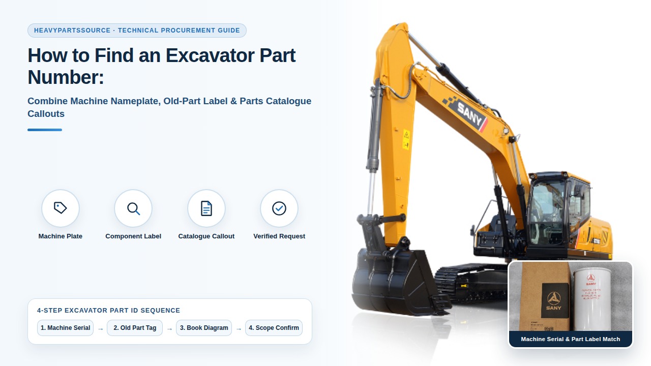
Ordering an excavator replacement part from a boom model decal or a raised housing casting mark alone causes wrong-part air-freight returns, port-thread mismatches, and multi-day machine downtime. Confirm the exact orderable part number by cross-locking the 17-character machine Product Identification Number (PIN) plate, the sub-vendor component data tag, and the serial-filtered OEM parts-book callout before releasing a purchase order.
To find and verify an excavator part number without fitment errors, record four separate technical records before requesting a quotation: (1) the 17-character machine Product Identification Number (PIN) defined under ISO 10261:2021 (or the 3-character serial prefix and sequential build number that govern mid-series OEM catalog breaks), (2) the sub-vendor component nameplate (which, as documented in the Danfoss H1P Service Parts Manual AX152986481244en-001004, March 2026, page 5, separates the complete assembly Ident number, the internal configuration model code, and the build serial number), (3) the illustrated OEM parts-book callout and scope (complete assembly versus bare subcomponent or seal kit), and (4) physical caliper measurements of DIN 5480 / ISO 4156 involute splines and ISO 6162-1 / ISO 6162-2 four-bolt flange ports whenever the component tag is missing. Never submit a raised foundry casting number as an orderable assembly part number.
Scroll horizontally to view all columns.
| Input or item | Standard baseline or source | Why it governs part-number verification |
|---|---|---|
| 17-character machine PIN and serial prefix | ISO 10261:2021 Clauses 4.1–4.7; cab plate (>= 4 mm text) or right-hand frame stamp (>= 6 mm text, >= 0.2 mm depth) | Selects the exact OEM bill of materials across mid-series production serial breaks |
| Sub-vendor component nameplate | Component housing tag (Danfoss AX152986481244en-001004, March 2026, p. 5) | Separates complete assembly part number, internal module code, and build serial |
| Raw foundry casting or forging mark | Raised or embossed characters (>= 0.5 mm relief) cast into raw iron or aluminum shells | Identifies only the unmachined mold cavity shared across multiple incompatible builds |
| Illustrated OEM parts-book callout | Caterpillar SIS, Komatsu CSS, Hitachi PartsPro, Volvo PROSIS, or SANY GSP diagram | Confirms whether an item number represents a complete assembly, bare housing, or repair kit |
Involute spline shaft geometry (z, m, W_k) | DIN 5480 / ISO 4156 / ANSI B92.1 (30 deg pressure angle, vernier caliper check) | Resolves pump, swing-motor, or travel-motor shaft codes when the component tag is sheared off |
4-bolt split-flange port pattern (L_long x L_short) | ISO 6162-1 (Code 61, 160–350 bar) vs. ISO 6162-2 (Code 62, 420 bar), measured within <= 1.0 mm | Prevents mismatching Code 61 and Code 62 ports that share the same nominal bore and O-ring |
| Requested supply scope | Buyer maintenance plan (Parker Cylinder Manual, p. 41, pp. 44–49) | Distinguishes a complete assembly from a rod/piston seal kit, bare cartridge, or hardware set |
| Dominant failure mode & prevention | Unverified decal or casting-mark ordering causing air-freight return and bay downtime | Prevented by locking PIN serial break + sub-vendor tag + catalog scope prior to dispatch |
How do the four excavator identification sources compare, and why do casting numbers fail?
An excavator carries multiple layers of numbering stamped, riveted, cast, or printed across the machine frame and its hydraulic and powertrain assemblies. Treating every visible number on an old part as an interchangeable ordering reference is the primary root cause of mis-shipped heavy equipment parts.
In heavy-equipment manufacturing, a raw iron or aluminum housing is cast at a foundry with a raised pattern or mold identifier—the casting number—before the casting enters CNC machining centers. The same raw casting shell is routinely finish-machined into several incompatible orderable part numbers with different internal displacements, pilot port threads, valve spools, or gear ratios. Only after machining, assembly, and test-stand calibration does the manufacturer rivet or laser-etch the assembly part number onto the component data plate.
Scroll horizontally to view all columns.
| Identification source | Physical appearance and location | What the number actually identifies | Reliability for direct ordering | Dominant failure mode & prevention |
|---|---|---|---|---|
Machine PIN plate & primary frame stamp (ISO 10261:2021) | Riveted plate near cab entry (>= 4 mm text) and deep stamping on right-hand front main frame (>= 6 mm text, >= 0.2 mm depth) | Exact machine model descriptor, check character, serial prefix, and sequential build number | High for machine-level OEM catalog filtering; does not show aftermarket sub-vendor swaps | Failure mode: Selecting the wrong mid-series OEM diagram when the cab plate is painted over. Prevention: Recover the deep-stamped primary PIN on the right-hand boom-foot frame and filter by exact serial break. |
Sub-vendor component nameplate (Danfoss / Kawasaki / Nabtesco / Cummins) | Riveted brushed-aluminum or laser-etched steel tag on pump regulator, motor casing, valve bank, or engine block | Complete component assembly P/N, internal build/model code string, and sub-vendor serial number | Highest for both complete replacement units and internal rotating groups, valve plates, or seal kits | Failure mode: Ordering internal pump or motor parts from the machine model alone after a previous owner swapped sub-vendor versions. Prevention: Photograph the component tag straight on and transcribe every line verbatim. |
Illustrated OEM parts-book callout (SIS / CSS / PartsPro / GSP) | Exploded assembly diagram with item callout number, serial-range header, quantity per assembly, and parent-child indentation | Orderable OEM service part number, supersession chain, and assembly vs. subcomponent hierarchy | High when locked to the machine's exact serial prefix and verified for assembly versus kit scope | Failure mode: Ordering an item callout that represents only a bare housing or bracket rather than the complete assembly. Prevention: Verify parent-child indentation and scope notes (complete unit vs. kit) on the catalog page. |
| Raw foundry casting or forging mark | Raised, molded, or coarse embossed characters (>= 0.5 mm relief) cast directly into raw iron, steel, or aluminum housings | Unmachined foundry mold cavity, core box, or raw forging die shared across multiple finished configurations | Unreliable as a standalone order number; maps to multiple incompatible displacements and port threads | Failure mode: Non-returnable shipment of an assembly with the wrong displacement, regulator, or gear ratio. Prevention: Log casting marks strictly in a separate observation field and cross-reference against the component tag and PIN. |
Physical caliper & port geometry check (DIN 5480 / ISO 6162) | Vernier caliper readings of spline tooth count z, tip OD d_a1, span W_k, and 4-bolt flange center spacing L_long x L_short | Mechanical mounting, shaft coupling, and hydraulic port interface envelope when labels are destroyed | Essential verification gate to eliminate candidate ambiguity when plates are missing | Failure mode: Spline coupling interference or crushed flange O-ring (Code 61 vs. Code 62) on untagged assemblies. Prevention: Measure bolt centers within <= 1.0 mm and spline span W_k to +/-0.05 mm before approving a candidate. |
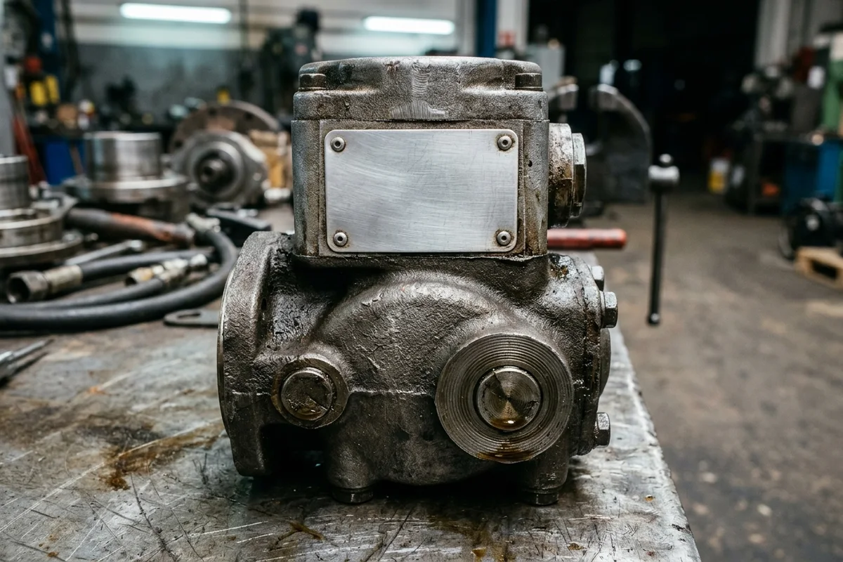
Contrast on a removed hydraulic pump assembly: the riveted aluminum data plate defines the finished assembly identity and internal model code, while the rough cast-iron shell carries only foundry mold markings.
Engineering Rule-of-Thumb (Foundry Casting Mark vs. Machined Assembly Threshold): If a number is raised or embossed above the raw cast-iron or aluminum surface by >= 0.5 mm rather than stamped or laser-etched onto a dedicated data plate under hydraulic pump, valve block, cylinder tube, or final-drive inspection → classify the number strictly as an unmachined foundry mold casting reference rather than an orderable part number, because a single raw housing casting is finish-machined across multiple displacements, thread standards, and relief settings.
Takeaway: Never enter a raised housing casting number into the confirmed part-number field of a purchase order; keep casting marks in a separate observation column alongside the component tag and machine PIN.
How does the 17-character ISO 10261 PIN and serial-prefix break control OEM catalog lookup?
A boom decal such as 320D, PC200-8, ZX200-5G, EC210B, or SY215C identifies only a commercial weight class and marketing generation. Across a multi-year production run, excavator manufacturers introduce mid-series engineering revisions—updating emission tiers, main hydraulic pump regulators, control-valve wiring harnesses, cylinder rod diameters, and undercarriage link pitches—without changing the painted model decal on the boom.
Under international standard ISO 10261:2021(E) (Earth-moving machinery — Product identification numbering system, Clauses 4.1–4.8), every earth-moving machine is assigned a continuous 17-character alphanumeric Product Identification Number (PIN) using numerals 0–9 and uppercase letters A–Z (with I, O, and Q excluded from Table 1 year codes so they cannot be misread as 1 or 0):
- World Manufacturer Code (WMC, Positions 1–3, Clause 4.4): Three alphanumeric characters registered to uniquely identify the equipment manufacturer.
- Machine Descriptor Section (MDS, Positions 4–8, Clause 4.5): Five alphanumeric characters encoding the machine family, series, and configuration attributes.
- Check Letter (CL, Position 9, Clause 4.7): A calculated verification character that detects single-digit transcription errors when the PIN is entered into an electronic catalog.
- Machine Indicator Section (MIS, Positions 10–17, Clause 4.6): Eight characters that isolate the individual machine build. Positions
10–13accept alpha or numeric characters (often encoding the model-year code from ISO 10261 Table 1 or the manufacturer's 3-character serial prefix), while positions14–17must be strictly numeric (0–9) to record the sequential production build number.
Under ISO 10261:2021 Clauses 5.2, 6.1, and 7, the riveted product plate near the operator cab access area uses characters at least 4 mm high, whereas the primary structural PIN is permanently stamped, engraved, or laser-cut directly into a non-replaceable section of the front right-hand main frame with a minimum character height of 6 mm and a minimum stamping depth of 0.2 mm. When a cab plate is abraded or painted over, scraping paint from the right-hand boom-foot frame stamping recovers the controlling serial number.
Scroll horizontally to view all columns.
| OEM catalog system | Primary lookup key required | Part-number syntax baseline | How serial breaks partition parts | Dominant failure mode & prevention |
|---|---|---|---|---|
Caterpillar SIS (SIS 2.0) | 3-character serial prefix + 5-digit sequential serial (last 8 characters of the 17-character PIN) + Arrangement No. | 7-digit (xxx-xxxx, e.g., 1R-0749) or 8-character alphanumeric | Identical model names (320D) split across dozens of factory prefixes (MGB, FAL, KGF) and serial-number breaks (S/N 00001–01499 vs. 01500-up) | Failure mode: Ordering by model decal without the 3-character prefix selects the wrong engine arrangement or pump control group. Prevention: Lock the full 8-character PIN suffix and engine arrangement number before selecting any diagram. |
Komatsu CSS ( Link / Parts Book) | Machine model + exact dash series (-6, -7, -8, -10) + sequential 5- or 6-digit machine serial number | 10-digit hyphenated (xxx-xx-xxxxx) or hardware code (07000-xxxxx) | Mid-series serial breaks (e.g., S/N 50001 and up) alter hydraulic pump sub-assemblies, seal kits, and cab harnesses within the same dash series | Failure mode: Mixing -7 and -8 dash generations or ignoring a mid-series serial break (<= 50000 vs. >= 50001). Prevention: Record both the dash suffix and exact frame serial number on every request line. |
| Hitachi PartsPro / John Deere | Full model code (including variant letters LC, H, K) + 17-character PIN / 6-digit serial number | 7- to 10-character numeric or alphanumeric (xxxxxxx or ATxxxxxx) | Serial-number ranges on each parts-book page header specify which component revision applies to early versus late production runs | Failure mode: Transcribing letter O as digit 0 or letter B as digit 8 on weathered plates. Prevention: Attach an unedited macro photograph of the plate (line-01-machine-pin.jpg) alongside typed text. |
| Volvo PROSIS / Doosan-Develon TMS | Machine model + manufacturing serial number (5- to 6-digit sequence) | 8-digit numeric (VOE xxxxxxxx) or 6- to 10-character alphanumeric | Component supplier transitions (such as travel-motor or main-valve revisions) are indexed strictly by sequential machine serial number | Failure mode: Assuming one final drive or main valve fits all serial numbers of an EC210B or DX225LC. Prevention: Verify both the machine serial break and the removed component's own data tag. |
SANY Global Service Portal (GSP) | Full 17-character machine PIN / serial number + model series (SY35U to SY365C) | 8- to 10-digit numeric material code (e.g., 60277731, 13987636, B222100000xxx) | Factory BOMs tie specific hydraulic pumps, controllers, and filtration kits to the individual machine PIN build list | Failure mode: Using a generic model brochure reference when the unit has a factory configuration update. Prevention: Cross-check the machine PIN and old component tag against our heavy equipment parts directory and the manufacturer reference portal. |
When you hold an OEM parts-book page, record its publication title, revision date, applicable serial-number range, figure number, and item callout number. The SANY parts portal is an example of a manufacturer reference entry point; referencing an OEM portal supports technical identification and does not establish HeavyPartsSource stock or manufacturer authorization.
Engineering Rule-of-Thumb (Machine PIN & Serial-Prefix Break Threshold): If an excavator's sequential serial number falls within ±500 units of a documented OEM mid-series production break (or if positions 10–13 of the 17-character ISO 10261 PIN are abraded on the cab plate) under multi-year fleet operation → recover the 6 mm deep-stamped primary frame PIN on the right-hand boom foot (>= 0.2 mm stamping depth per ISO 10261:2021 Clause 7) and verify the installed component's own nameplate before ordering, because factory transition units and field retrofits frequently cross catalog serial boundaries.
Takeaway: Always pair the machine model with its full 17-character ISO 10261 PIN (or 3-character prefix and sequential serial number) and the catalog page's applicable serial range.
Why must you record the sub-vendor component data tag alongside the excavator PIN?
An excavator's machine PIN tells you how the excavator left the OEM assembly plant, but major hydraulic, drivetrain, and engine assemblies are manufactured by specialized tier-1 sub-vendors—such as Kawasaki Precision Machinery (KPM), Bosch Rexroth, Danfoss, Kayaba (KYB), Nabtesco, Cummins, Isuzu, or Weichai. Recording the sub-vendor nameplate is mandatory for two engineering reasons: first, OEM parts books often list only the top-level excavator part number while indexing internal repair parts by the sub-vendor's build code; second, a high-hour excavator may have had a replacement pump, motor, or engine installed during a previous overhaul.
In the Danfoss H1P 210, 250, and 280cc Axial Piston Pump Service Parts Manual (AX152986481244en-001004, March 2026, page 5, Service parts identification — Nameplate), the manufacturer documents the three distinct fields stamped on a hydraulic pump nameplate and explains why each serves a different procurement function:
- Model / Material Number (Ident No., e.g.,
83038133): The factory material number that identifies the complete, fully configured unit. On repeat or replacement orders, a complete assembly is ordered using this material number. - Model Code String (e.g.,
H1P250 R A A A3 C1 N D8 C F8 E2 L 42 L 42 W P 24 PN NNN NNN): The alphanumeric configuration string that completely defines every internal module group—rotation (R/L), displacement control (A3), shaft spline option (A4–G3), end cap porting (D6, D8, J1), housing (C, E), auxiliary mounting pad (F8, E1–E2, H1–H2), and port A/B high-pressure relief settings (L42). The manual specifies that this complete model code must be used when ordering internal service parts. - Component Serial Number (Plant letter + 2-digit year + 2-digit calendar week + 5-digit sequence): Identifies the exact manufacturing week and unit sequence, which determines whether internal components fall before or after engineering service bulletins (such as
SB-2020-013orSB-2024-007on pages 2 and 129–138).
The same multi-field rule governs every major excavator subsystem on our platform:
- Hydraulic main pumps and control valves: Before comparing quotes in the hydraulic pumps category, follow the replacement hydraulic pump verification checklist to capture the pump nameplate, regulator tag, auxiliary gear-pump tag, and whether you need a bare pump or a complete assembly with regulator and auxiliary sections.
- Final drives and travel motors: A crawler excavator drive combines a hydraulic travel motor and a planetary reduction gearbox. Use the excavator final drive assembly scope guide and our final drives category to photograph both the motor tag and the gearbox tag and specify whether the request covers the motor only, the gearbox only, or the bolted complete assembly.
- Hydraulic cylinder seal kits: As documented in Parker's Cylinder Parts Identification and Seal Kit Data Manual (page 41 and pages 44–49) and SKF's Hydraulic Seals Catalogue (PUB SE/P1 12393/3 EN, February 2026, page 11), bore and rod diameters alone do not identify seal groove geometry, profile, or compound. Use our hydraulic cylinder seal kits by size guide and the seal kits category to record the stamped cylinder barrel/head part number, earlier kit bag reference, and scope (
complete cylinder,rod gland, orpiston). - Diesel engines and filtration stages: An excavator frame plate does not replace the engine data plate mounted on the valve cover or crank block. Follow the diesel engine parts identification guide to record the engine family, arrangement/CPL code, and engine serial number. When ordering spin-on or cartridge elements from the filters category, Donaldson's Engine Liquid Filtration Product Guide (F110024-ENG, page 58) cautions against consolidating filter part numbers across machines by thread and outer diameter alone because micron efficiency, bypass valve cracking pressure, and OEM updates remain application-specific.
Takeaway: Always photograph and transcribe both the excavator frame PIN plate and the removed component's own sub-vendor nameplate; never assume the machine model alone defines internal pump, motor, cylinder, or engine components.
How do you verify spline shafts and hydraulic flange ports when a component tag is missing?
On excavators working in demolition, quarry, forestry, or trenching service, riveted aluminum component tags on travel motors, swing motors, and hydraulic pumps are frequently sheared off by rock impact, heavy corrosion, or sandblasting. When the component tag is missing and the machine PIN maps to two possible OEM sub-vendor options, physical caliper verification of the drive shaft involute spline and four-bolt hydraulic split-flange ports provides the deterministic engineering baseline needed to eliminate the wrong candidate before shipping.
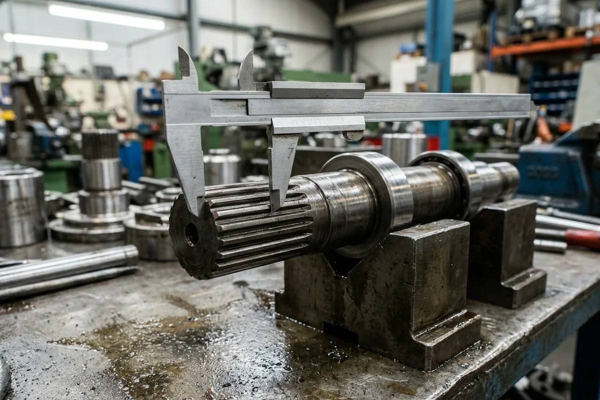
Measuring external involute spline tip diameter and span across teeth on a machined drive shaft resting on V-blocks when a component nameplate is missing.
1. Involute Spline Pitch Diameter, Base Circle & Caliper Span Equation (DIN 5480 / ISO 4156)
Heavy-equipment hydraulic pumps and motors predominantly use DIN 5480, ISO 4156, or ANSI B92.1 involute splines with a standard 30 deg pressure angle (alpha = 30 deg), module m (1.25 mm, 1.5 mm, 1.75 mm, 2.0 mm, 2.5 mm, or 3.0 mm), and integer tooth count z. Under DIN 5480 (DIN 5480 - W d_B x m x z), the pitch circle diameter d, base circle diameter d_b, shaft tip diameter d_a1, and vernier caliper span measurement W_k across k external teeth follow the exact geometric equations:
d = m * z, d_b = m * z * cos(alpha), d_a1 = m * z + 2 * x * m + 0.9 * m
W_k = m * cos(alpha) * [ pi * (k - 0.5) + z * inv(alpha) ] + 2 * x * m * sin(alpha)
where inv(alpha) = tan(alpha) - alpha_rad is the involute function (for alpha = 30 deg = 0.523599 rad, cos(30 deg) = 0.866025, sin(30 deg) = 0.500, and inv(30 deg) = 0.577350 - 0.523599 = 0.053751 rad), and x * m is the profile shift (-0.05*m to +0.45*m on DIN 5480 shafts).
- Worked Example (21-Tooth vs. 22-Tooth Hydraulic Pump Shaft Verification): Suppose an untagged excavator main pump shaft has module
m = 2.0 mm, counted teethz = 21, pressure anglealpha = 30 deg, profile shiftx * m = +0.10 mm(DIN 5480 - W 45 x 2 x 21), and a technician measures the span acrossk = 3teeth with vernier caliper jaws:d = 2.0 * 21 = 42.00 mm, d_b = 42.00 * 0.866025 = 36.37 mm, d_a1 = 42.00 + 2(0.10) + 0.9(2.0) = 44.00 mm
RecordingW_3 = 2.0 * 0.866025 * [ 3.141593 * (3 - 0.5) + 21 * 0.053751 ] + 2 * 0.10 * 0.500 = 1.73205 * [ 7.85398 + 1.12877 ] + 0.100 = 15.66 mmz = 21,d_a1 = 44.00 mm, andW_3 = 15.66 mmimmediately separates thisW 45 x 2 x 21shaft from aW 45 x 2 x 22shaft (which hasz = 22andW_3 = 15.75 mm).
Engineering Rule-of-Thumb (Involute Spline Module & Tooth Count Threshold): If a component nameplate is missing and the measured shaft tip diameter d_a1 differs by >= 0.8 mm from the nominal catalog shaft diameter (or the counted spline teeth z differ by >= 1 tooth across a 12- to 28-tooth DIN 5480 / ISO 4156 / ANSI B92.1 spline) under replacement pump or motor verification → record the exact integer tooth count z, shaft tip diameter d_a1, and caliper span W_k across k teeth to ±0.05 mm before ordering, because a 1-tooth or 0.25 mm module mismatch prevents coupling engagement with the flywheel or planetary carrier.
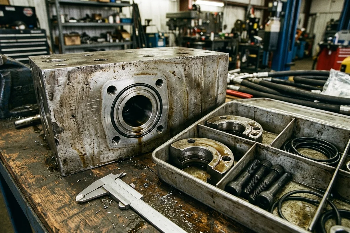
Four-bolt split-flange port face on a hydraulic block beside split-flange clamps, socket bolts, O-ring seals, and a vernier caliper used to verify Code 61 versus Code 62 bolt-hole spacing.
2. Four-Bolt Hydraulic Split-Flange Port Verification (ISO 6162-1 Code 61 vs. ISO 6162-2 Code 62)
High-pressure excavator pump discharge ports, main control valve ports, and travel-motor supply/return lines use four-bolt split-flange connections governed by ISO 6162-1 (SAE J518 Code 61, 3000 Series) and ISO 6162-2 (SAE J518 Code 62, 6000 Series). At any given nominal flange size (1/2" to 2"), Code 61 and Code 62 share the exact same nominal bore and the exact same ISO 3601-1 / AS568 O-ring (3.53 mm cross-section), but their rectangular bolt-hole center spacings (L_long x L_short) and flange-head thicknesses are non-interchangeable:
Scroll horizontally to view all columns.
| Nominal flange size (DN / Dash) | Series (ISO 6162 / SAE J518) | Standard working pressure baseline | Bolt-hole center spacing L_long x L_short | Standard fastener thread (Type 2 UNC / Type 1 Metric) | Shared O-ring (ISO 3601-1 / AS568, 3.53 mm section) | Dominant failure mode & prevention |
|---|---|---|---|---|---|---|
1/2" (DN 13 / -08) | Code 61 (ISO 6162-1) | 350 bar (5000 psi) | 38.1 × 17.5 mm (1.500 × 0.688 in) | 5/16"-18 UNC or M8 | #210 (18.64 × 3.53 mm) | Failure mode: Eyeballing a 1/2" port misses the 2.4 mm long-axis difference between Code 61 (38.1 mm) and Code 62 (40.5 mm). Prevention: Measure bolt centers with a caliper to <= 1.0 mm per ISO 6162-1. |
1/2" (DN 13 / -08) | Code 62 (ISO 6162-2) | 420 bar (6000 psi) | 40.5 × 18.2 mm (1.594 × 0.718 in) | 5/16"-18 UNC or M8 | #210 (18.64 × 3.53 mm) | Failure mode: Stripping M8 metric port threads by forcing 5/16"-18 UNC bolts. Prevention: Check for the 'M' stamp on Type 1 metric ports and verify thread pitch before assembly. |
3/4" (DN 19 / -12) | Code 61 (ISO 6162-1) | 350 bar (5000 psi) | 47.6 × 22.2 mm (1.875 × 0.875 in) | 3/8"-16 UNC or M10 | #214 (24.99 × 3.53 mm) | Failure mode: Ordering a Code 61 pump end cap when the machine hoses use Code 62 (50.8 × 23.8 mm) high-pressure flanges. Prevention: Record both L_long and L_short on the port face. |
3/4" (DN 19 / -12) | Code 62 (ISO 6162-2) | 420 bar (6000 psi) | 50.8 × 23.8 mm (2.000 × 0.937 in) | 3/8"-16 UNC or M10 | #214 (24.99 × 3.53 mm) | Failure mode: Using an identical #214 O-ring as false proof that the flange clamps match. Prevention: Never identify flange series from the O-ring ID (24.99 mm); always measure the 4-bolt rectangle. |
1" (DN 25 / -16) | Code 61 (ISO 6162-1) | 320 bar (5000 psi) | 52.4 × 26.2 mm (2.062 × 1.031 in) | 3/8"-16 UNC or M10 | #219 (32.92 × 3.53 mm) | Failure mode: Derating burst margin by installing a 320 bar Code 61 port body on a 420 bar main discharge circuit. Prevention: Verify 52.4 × 26.2 mm (M10) vs. 57.2 × 27.8 mm (M12). |
1" (DN 25 / -16) | Code 62 (ISO 6162-2) | 420 bar (6000 psi) | 57.2 × 27.8 mm (2.250 × 1.094 in) | 7/16"-14 UNC or M12 | #219 (32.92 × 3.53 mm) | Failure mode: Cocking the clamp half on a thicker Code 62 flange head and crushing the #219 O-ring under pressure spikes. Prevention: Match both the 57.2 × 27.8 mm pattern and M12 (7/16"-14) bolt holes. |
1-1/4" (DN 32 / -20) | Code 61 (ISO 6162-1) | 280 bar (4000 psi) | 58.7 × 30.2 mm (2.312 × 1.188 in) | 7/16"-14 UNC or M10/M12 | #222 (37.69 × 3.53 mm) | Failure mode: Mismatching suction/return Code 61 ports (58.7 × 30.2 mm) with high-pressure Code 62 discharge ports (66.7 × 31.8 mm). Prevention: Measure each port (A, B, suction, case drain) individually. |
1-1/4" (DN 32 / -20) | Code 62 (ISO 6162-2) | 420 bar (6000 psi) | 66.7 × 31.8 mm (2.625 × 1.250 in) | 1/2"-13 UNC or M12/M14 | #222 (37.69 × 3.53 mm) | Failure mode: Ordering a replacement pump or motor without specifying metric (M) vs. inch (UNC) flange bolt threads. Prevention: Inspect the port face for the ISO 6162 'M' stamp and measure bolt thread pitch. |
Engineering Rule-of-Thumb (ISO 6162 Code 61 vs. Code 62 4-Bolt Split-Flange Threshold): If the long-axis bolt-hole center spacing L_long on a 1-inch (DN 25 / -16) excavator hydraulic port measures > 54.0 mm (specifically 57.2 × 27.8 mm rather than 52.4 × 26.2 mm, measured within <= 1.0 mm per ISO 6162-1) under 350–420 bar main-pump or travel-motor line pressure → specify an ISO 6162-2 (SAE J518 Code 62, 420 bar) flange interface with M12 or 7/16"-14 fasteners rather than ISO 6162-1 (Code 61, 320 bar), because forcing a mismatched split clamp onto the flange head cocked at an angle crushes the 3.53 mm cross-section #219 O-ring and causes high-pressure port blow-out.
Takeaway: When a component tag is missing or incomplete, pair your photos with vernier caliper readings of the spline tooth count z, shaft tip OD d_a1, span W_k, and 4-bolt flange spacing L_long x L_short within ±1.0 mm.
What does a wrong part number cost in excavator downtime and air-freight returns?
Guessing an illegible digit on a corroded tag or ordering a heavy hydraulic pump, final drive, or track chain from a casting mark saves 15 minutes during inquiry preparation but exposes the maintenance budget to severe total cost of ownership (TCO) penalties when the crate arrives at the jobsite and fails to bolt up.
Wrong-Part Excavator Downtime & Return Air-Freight Cost Equation
The total financial loss C_mismatch from a single misidentified heavy-equipment assembly combines machine standby downtime, two-way international freight on heavy cast-iron hardware, supplier restocking fees, and duplicate workshop bay labor:
C_mismatch = (D_delay * H_shift * R_downtime) + (2 * W_ship * R_freight) + (P_part * f_restock) + C_labor
where D_delay is the net replacement delay in working days, H_shift is scheduled operating hours per day, R_downtime is the hourly standby cost of the idled excavator and crew ($/h), W_ship is the crated shipping weight (kg), R_freight is the one-way expedited air-freight rate ($/kg), P_part is the invoice price of the misordered assembly ($), f_restock is the supplier restocking/re-inspection fee fraction, and C_labor is the wasted mechanic bay labor for failed fit-up and re-crating ($).
- Worked Example (
145 kgExcavator Main Hydraulic Pump Misordered via Foundry Casting Mark): Assume a buyer orders a145 kgmain hydraulic pump (P_part = $4,800) using a raised housing casting mark without checking the machine PIN serial break, resulting in the wrong regulator and spline shaft. If air-freight return and re-dispatch addD_delay = 6 daysatH_shift = 8 h/dayandR_downtime = $165/h, with international air freight atR_freight = $8.50/kg, af_restock = 15%(0.15) restocking fee, andC_labor = $640(8 man-hours × $80/h):
A single unverified part number generates $11,745 in avoidable downtime and return freight—more thanC_mismatch = (6 * 8 * 165) + (2 * 145 * 8.50) + (4800 * 0.15) + 640 = $7,920 + $2,465 + $720 + $640 = $11,7452.4xthe purchase price of the hydraulic pump itself.
Scroll horizontally to view all columns.
| 5-Year Fleet Procurement TCO Dimension | Unverified Model-Decal / Casting-Mark Ordering | 4-Point PIN + Sub-Vendor Tag + Catalog + Caliper Verification | Primary Cost Driver & Operational Impact | Dominant Failure Mode & Prevention |
|---|---|---|---|---|
Heavy hydraulic & drivetrain air-freight returns (80–350 kg per unit) | 8%–14% first-shipment fitment mismatch rate across mixed serial ranges | < 1% mismatch rate; open differences held at candidate status before dispatch | Round-trip air freight ($8–$12/kg) plus customs re-entry duties on heavy iron assemblies | Failure mode: Paying two-way international air freight on a 200 kg final drive with the wrong sprocket bolt circle. Prevention: Complete the final drive scope table and verify tag + bolt circle before shipping. |
| Unplanned excavator jobsite standby downtime | 5–14 extra days per misordered major component while waiting for re-shipment | 0 extra re-shipment days; correct serial-break assembly dispatched on first shipment | Idled 20–36 ton excavator standby loss ($120–$220/h in rental replacement and crew stall) | Failure mode: Machine parked with boom cylinders or travel motors removed in an active bay. Prevention: Lock the 17-character ISO 10261 PIN and sub-vendor tag via our part identification service. |
| Companion seal, O-ring, and mounting hardware stalls | Missing flange O-rings (#214, #219, #222), cover gaskets, or metric bolts halt reassembly | Companion seal kits and flange hardware itemized on the same quotation line | A missing $15 ISO 6162 flange O-ring or seal kit delays commissioning of a $5,000 pump | Failure mode: Ordering a bare element or pump without its companion mounting seal kit. Prevention: Specify assembly versus kit scope using the seal kit worksheet. |
| Undercarriage & multi-brand fleet consolidation errors | Ordering track chains by shoe width alone or merging similar filters across engines | Pitch, link count, bolt hole size, and per-machine serial references kept in separate rows | Wrong link pitch (190 mm vs. 203 mm) or incompatible filter media causes rapid wear | Failure mode: Consolidating part numbers across different machines by visual appearance. Prevention: Use the excavator track chain fitment checklist and multi-brand parts list guide. |
| Pre-dispatch quality & dimensional verification | Blind box-forwarding with no label, port, or spline verification prior to export | Agreed pre-dispatch quality checks on part label, quantity, and visible interface geometry | Catching a warehouse picking error before air or sea dispatch eliminates site rework | Failure mode: Discovering a superseded or misboxed part only after customs clearance at destination. Prevention: Require pre-dispatch tag and interface photo confirmation under our parts sourcing service. |
Takeaway: Spending 20 minutes to capture the 17-character machine PIN, the sub-vendor component tag, the catalog scope, and caliper interface dimensions eliminates five-figure downtime and air-freight return losses.
Copy the excavator part number and PIN verification worksheet
Edit the worksheet below, copy it, and paste it into your inquiry or fleet purchasing spreadsheet. Use one worksheet block per major assembly (or combine multiple verified lines using our multi-brand consolidation service). Leave any unverified field marked as Unknown rather than guessing an unreadable character.
Scroll horizontally to view all columns.
| Worksheet section | What to record | How to handle missing or damaged data |
|---|---|---|
1. Machine identity (ISO 10261:2021) | Brand, full model with dash series, and all 17 characters of the PIN (or 3-character prefix + sequential serial) | If the cab plate is illegible, check the 6 mm deep stamping on the right-hand front boom-foot frame |
| 2. Sub-vendor component nameplate | Component position, sub-vendor brand, complete assembly Ident No., full model code string, and component serial | Mark any scratched digit with [?] and attach an unedited macro photo (line-01-component-tag.jpg) |
| 3. OEM catalog & casting marks | Manual publication code, revision, serial range, figure/item callout, and any raised foundry casting marks | Keep raised housing casting marks in the foundry observation line—never copy them into the confirmed P/N field |
| 4. Physical caliper fallback | Spline tooth count z, shaft tip OD d_a1, span W_k, and 4-bolt flange spacing L_long x L_short (±1.0 mm) | Record only measurements taken with a caliper on clean metal; mark unmeasured features as Unknown |
| 5. Scope & photo filenames | Whether you need a complete assembly, bare subcomponent, or repair seal kit, plus line-numbered photo names | Follow the photo checklist for part identification so each image maps to one request line |
Takeaway: Separating confirmed tag numbers, catalog callouts, foundry casting marks, and caliper measurements on one worksheet prevents unverified guesses from corrupting your order.
Frequently asked questions about finding excavator part numbers
Can you find an excavator part number from the machine serial number alone?
A machine's 17-character ISO 10261 PIN or serial number isolates the original factory bill of materials in OEM catalogs (such as Caterpillar SIS, Komatsu CSS, or SANY GSP). However, for internal hydraulic pump, travel-motor, cylinder, or engine components—or on machines where an assembly was previously replaced—you must also record the sub-vendor component nameplate.
Why does a casting number on an excavator hydraulic pump or final drive not match the parts catalog?
A raised or embossed casting number (>= 0.5 mm relief) identifies the raw, unmachined iron or aluminum foundry mold cavity, not the finished assembly. Manufacturers machine the same raw housing casting into multiple part numbers with different displacements, port threads, and regulator settings, so OEM parts catalogs index only the finished assembly part number.
How do you read an excavator part number when the component data plate is scratched or painted over?
Clean paint or grease using solvent and a soft cloth rather than a wire wheel or scraper, then photograph the plate under angled side lighting to reveal stamped indentations (>= 0.2 mm deep). Transcribe readable characters, mark any uncertain digit with [?], and measure the spline shaft (z, d_a1, W_k) and 4-bolt flange spacing (L_long x L_short) with calipers.
Does an OEM parts catalog callout include companion O-rings, mounting bolts, or sub-assemblies?
Not automatically. In OEM exploded diagrams, a parent item number may designate a complete assembly while indented child numbers designate bare housings, internal cartridges, or separate ISO 6162 flange O-ring and seal kits (Parker Cylinder Manual, pp. 41, 44–49). Always state whether your request line requires the complete assembly, a bare subcomponent, or the companion repair seal kit.
What to send us
Scroll horizontally to view all columns.
| Item | Why we need it | Example format |
|---|---|---|
| 17-character machine PIN / serial plate record | Locks the exact OEM serial-number break and model configuration (ISO 10261:2021) | line-01-machine-pin.jpg plus typed 17-character PIN or prefix + serial |
| Sub-vendor component nameplate photo & text | Identifies the complete assembly Ident No., internal model code string, and sub-vendor serial (Danfoss AX152986481244en-001004, p. 5) | line-01-component-tag.jpg plus verbatim transcription of all tag lines |
| OEM parts-book page, revision & item callout | Confirms the diagram reference, applicable serial range, and parent-child scope | PDF page or screenshot showing manual title, revision, figure, and item number |
| Raw foundry casting marks (kept separate) | Provides secondary housing mold evidence when the riveted nameplate is damaged | line-01-casting-mark.jpg logged strictly in the casting observation field |
| Caliper spline & flange fallback measurements | Resolves untagged pump, motor, or valve variants (DIN 5480 spline z, d_a1, W_k and ISO 6162 bolt spacing L_long x L_short) | Typed millimeter readings with measurement points noted on the worksheet |
| Requested supply scope, quantity & destination | Defines whether to quote a complete assembly, bare subcomponent, or repair seal kit (Parker p. 41) | Completed worksheet line stating scope, quantity, and destination port/country |
A match in our catalog search is a starting point for verification, not a standalone compatibility approval. Whether or not a number appears in search, send your completed identification package for quotation review with the machine PIN, sub-vendor component tag, catalog callout, casting observations, caliper fallback readings, and requested supply scope listed above. Follow our part photography checklist to label your image files, and review how our parts sourcing and quotation process works to see how HeavyPartsSource verifies candidate offers and states the offered manufacturer, scope, and delivery terms in writing before any order is placed.
Takeaway: Submitting the machine PIN, sub-vendor component nameplate, catalog callout, and caliper fallback measurements in one line-numbered package lets HeavyPartsSource verify fitment and confirm the exact scope in writing before you place an order.
Method and sources
This engineering identification guide and verification worksheet were compiled from international machinery and fluid-power standards, published OEM service parts manuals, and HeavyPartsSource's documented procurement workflow, reviewed October 2026:
- ISO 10261:2021(E), Earth-moving machinery — Product identification numbering system (Third edition, August 2021, Clauses 4.1–4.9, 5.1–5.3, 6.1–6.2, and 7): 17-character PIN structure (WMC positions 1–3, MDS positions 4–8, Check Letter position 9, MIS positions 10–17), exclusion of letters
I,O, andQin year codes,>= 4 mmproduct-plate character height, and>= 6 mm(>= 0.2 mmdepth) right-hand front frame primary stamping requirements. - Danfoss H1P 210, 250, and 280cc Axial Piston Pump Service Parts Manual (Document No. AX152986481244en-001004, March 2026, pages 2–5 and 129–138): sub-vendor nameplate separation between the complete unit Model/Material (Ident) Number, the module-defining Model Code string, and the sequential Serial Number governing service bulletin breaks.
- ISO 6162-1 / ISO 6162-2 and SAE J518 Four-Bolt Hydraulic Split-Flange Standards (Code 61 standard series
160–350 barvs. Code 62 high-pressure series420 bar/6000 psi, together with ISO 3601-1 / AS568 O-ring dimensions): rectangular bolt-hole center spacings (L_long x L_short) from1/2"to1-1/4", the<= 1.0 mmmeasurement rule, Type 1'M'metric port marking versus Type 2 UNC threads, and shared3.53 mmcross-section O-rings (#210,#214,#219,#222). - DIN 5480 / ISO 4156 / ANSI B92.1 Involute Spline Standards (referenced via eAssistant / DIN 5480 engineering calculation manual, Section 17, retrieved October 2026):
30 degpressure-angle involute spline callout syntax (W d_B x m x z), pitch circle diameterd = m * z, base circle diameterd_b = m * z * cos(30 deg), profile shiftx * m, and base tangent span measurementW_kacrosskteeth. - Parker Cylinder Parts Identification and Seal Kit Data Manual (pages 41 and 44–49), SKF Hydraulic Seals Catalogue (PUB SE/P1 12393/3 EN, February 2026, page 11), and Donaldson Engine Liquid Filtration Product Guide (Catalog No. F110024-ENG, page 58): cylinder symbol/item callout requirements, standard vs. rod/piston seal kit scope separation, and the caution against consolidating part numbers across machines by external dimensions alone.
- HeavyPartsSource heavy equipment parts directory, part identification service, parts sourcing service, multi-brand consolidation service, and quality checks pages, verified October 2026.