
Publisher: HeavyPartsSource
An excavator final drive (track drive assembly) is a dual-chamber hydro-mechanical propulsion unit bolted to the crawler undercarriage frame that converts high-pressure hydraulic flow (31.4 to 35.0 MPa from the main pump via the center swivel joint) into low-speed, high-torque drive sprocket rotation (8.8 to 68.4+ kN*m). Because heavy-equipment suppliers use "final drive" to mean either the complete bolted drive unit (hydraulic travel motor + planetary reduction gearbox), the outboard planetary reduction gearbox (travel reducer) alone, or the inboard swashplate axial-piston hydraulic travel motor alone, comparing two replacement quotes without locking the exact mechanical supply scope causes $3,500 to $12,000 in rework, cross-contaminated API GL-5 gear hubs, premature outer duo-cone seal failure within 10–30 hours, and unplanned machine downtime.
Mechanically, every complete excavator final drive combines two distinct, fluid-isolated sub-assemblies inside one structural hub: (1) the inboard Hydraulic Travel Motor Hub (variable-displacement swashplate axial-piston rotary group + counterbalance brake valve + 2-speed shift spool + wet multi-disc parking brake, lubricated by ISO VG 46 hydraulic fluid at <= 2.0–3.0 bar case pressure), and (2) the outboard Planetary Reduction Gearbox Hub (2-stage or 3-stage epicyclic sun, planet, and ring gear train rated under ISO 6336 + main angular-contact bearings + Duo-Cone floating face seal, lubricated by an isolated bath of API GL-5 SAE 80W-90 / 85W-140 extreme-pressure gear oil).
Scroll horizontally to view all columns.
| Verification Layer / Scope Input | How to Measure or Transcribe on the Bench | Governing Standard / OEM Baseline | Dominant Failure Mode & Prevention |
|---|---|---|---|
| 1. Travel Device Nameplate & Machine 17-Char PIN | Photograph riveted tag on travel motor housing (10–25 deg raking light) + machine PIN plate (SY215C, SK200-8, DX225LC, PC200-8) | ISO 10261:2021 17-char PIN; OEM tags (Nabtesco GM35VL / GM38VB, Kayaba KYB MAG-170VP / MAG-180VP, Doosan Mottrol TM40VC, Eaton JMV-155, Rexroth GFT) | Failure mode: Ordering by excavator model decal alone across mid-series vendor switches (KYB MAG-170VP vs. Nabtesco GM35VL). Prevention: Lock both the travel drive tag string and 17-char machine PIN. |
2. Quoted Supply-Scope Envelope (ISO 8000-110 UOM) | Separate Complete Final Drive ASSY (Motor + Gearbox) from Planetary Gearbox Only, Hydraulic Travel Motor Only, or Duo-Cone Seal & Carrier Kit | ISO 8000-110 semantic UOM (ASSY vs. SUB-ASSY vs. KIT); HeavyPartsSource final drives & travel motors scope matrix | Failure mode: Accepting a low price quote that covers only the bare planetary gearbox when the hydraulic travel motor rotary group is bypassing internally. Prevention: Require explicit written scope across motor, gearbox, valve block, and sprocket hardware. |
3. Track-Frame Mounting Pilot (B) & Bolt Circle (D) | Measure motor flange pilot register OD B (mm), frame bolt circle diameter D (mm center-to-center), hole count, and thread pitch | Metric caliper metrology (+/- 0.1 mm); typical 20-ton class: 12, 16, 18, 20, or 24 frame bolts on 320–410 mm BCD | Failure mode: Drive assembly cannot seat into the excavator track frame bore or bolt holes misalign by 1–2 holes across serial breaks. Prevention: Measure Pilot OD B, Frame BCD D, and exact bolt hole count before dispatch. |
4. Drive-Sprocket Hub Pilot (A), BCD (C) & Offset (E) | Measure rotating gearbox hub pilot OD A (mm), sprocket BCD C (mm), threaded hole count, and flange-to-sprocket axial offset E (mm) | Metric caliper & depth-bar metrology (Dimensions A, C, E); typical 20-ton class: 12, 15, 16, 18, or 20 sprocket bolts | Failure mode: Existing drive sprocket will not register on the new planetary hub, or wrong axial offset E misaligns the sprocket with the track chain and rollers. Prevention: Verify A, C, and E against the removed drive and sprocket drawing. |
5. Rear Hydraulic Port Layout (3-Hose vs. 4-Hose) | Count rear/side ports and measure thread/flange standards: Main Flow A & B, Case Drain C / Dr1 / Dr2, and 2-Speed Pilot P_s | ISO 6162 split flange / JIS B 2351 (G / BSPP) / ISO 11926 (ORB); 3-port (1-speed / auto-shift) vs. 4-port (external 2-speed pilot) | Failure mode: Shipping a 3-port travel motor for a 4-hose 2-speed excavator harness, leaving the rabbit/turtle 2-speed pilot line disconnected or plugged. Prevention: Photograph the rear cover plate with hoses tagged before removal. |
6. Planetary Ratio (i_total) & Displacement (V_g) | Verify 2/3-stage reduction ratio i_total = i_1 * i_2 (1:36 to 1:84) and 2-speed motor displacement V_g,Lo / V_g,Hi (cm3/rev) | ISO 6336 planetary gear capacity; SAE J1995 power/torque matching; bilateral track speed match within <= 2% (never > 3%–5%) | Failure mode: Installing a 1:43.2 aftermarket drive opposite an OEM 1:46.8 drive (8.3% speed mismatch), causing continuous machine steering drift ("dog-walking"). Prevention: Match i_total and V_g to the opposite side drive. |
7. Dual-Chamber Fluid Isolation (GL-5 vs. VG 46) | Separate planetary gear bath (API GL-5 SAE 80W-90, 50–100 h break-in drain) from motor case-drain loop (ISO VG 46, P_case <= 2.0–3.0 bar) | API GL-5 / SAE J306 EP gear oil; ISO 4406 <= 18/16/13 hydraulic cleanliness; 15Cr3Mo / ASTM A532 Duo-Cone floating face seal | Failure mode: High case-drain pressure (> 2–3 bar) from a clogged inline filter or worn motor blows the inner shaft seal, pumping hydraulic oil into the gear hub and popping the outer duo-cone seal in 10–30 h. Prevention: Test case-drain pressure/flow and replace inline case-drain filters. |
1. How Does an Excavator Final Drive Work? Dual-Chamber Hydro-Mechanical Architecture
A crawler excavator cannot connect a high-speed hydraulic motor directly to its track drive sprocket: an axial-piston motor operating at 1,800 to 3,200 rpm develops high rotational speed but only 300 to 950 N*m of raw shaft torque, whereas moving a 20-ton to 36-ton excavator up a 35 deg (70%) grade or turning in packed rock requires 34,000 to 68,000+ N*m (34 to 68+ kN*m) at the sprocket. To bridge that torque gap inside the tight envelope of the track frame, every modern excavator final drive bolts two specialized hubs into a single structural core:
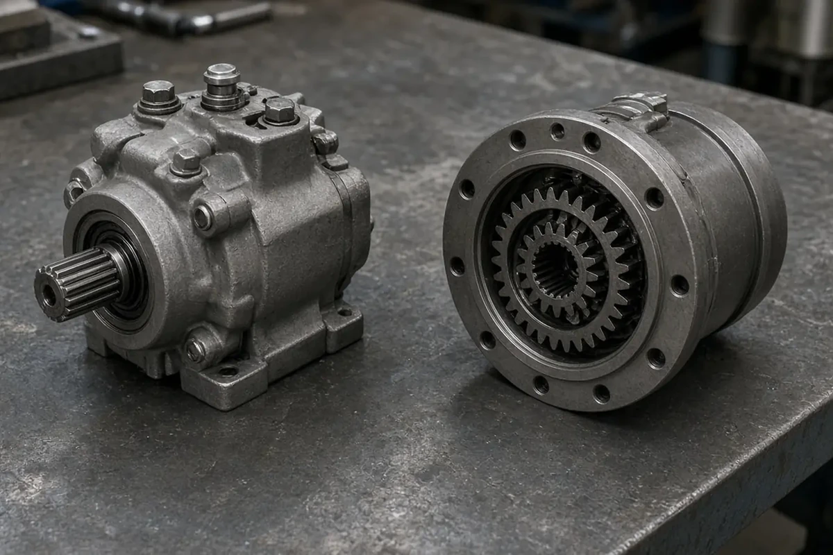
Figure 1: The two functional halves of an excavator final drive separated on the inspection bench—the inboard swashplate axial-piston hydraulic travel motor with its splined sun-gear drive shaft (left) and the outboard multi-stage planetary reduction gearbox hub that bolts to the track drive sprocket (right).
Sub-Assembly A: The Inboard Hydraulic Travel Motor Hub (Line Side)
Positioned inside the protective steel cavity of the undercarriage track frame where the hydraulic hoses connect via the center swivel joint (rotary manifold), the hydraulic travel motor hub contains four integrated subsystems:
- Variable-Displacement Swashplate Axial-Piston Rotary Group: Pressurized hydraulic oil (
31.4 to 35.0 MPa/314 to 350 bar) from the main hydraulic pump enters the rear port block and pushes nine precision-lapped pistons (2 to 5 umradial clearance inside a bronze-lined steel cylinder barrel) against an angled swashplate. As the cylinder barrel rotates against a bimetal spherical valve plate, its centerDIN 5480 / JIS B 1603involute splined output shaft transmits high-speed rotation into the first-stage sun gear of the planetary gearbox. - Two-Speed Swashplate Displacement Shift Mechanism (
Lo / HiMode): In Low-Speed / High-Torque mode (Turtle), the swashplate sits at its maximum tilt angle, delivering maximum geometric displacementV_g,Lo(e.g., 170.0 to 192.7 cm3/revon aKayaba MAG-170VPor140.5 cm3/revon aNabtesco GM35VL). When the operator selects High-Speed travel (Rabbit) and tracking pressure stays below the auto-downshift threshold, a3.5 to 4.0 MPapilot signal (Port P_s) shifts the two-speed spool and servo piston, tilting the swashplate to a shallower angle (V_g,Hi, typically55% to 65%ofV_g,Lo) to increase track speed by45% to 75%at reduced torque. - Counterbalance Valve (
Motion-Control / Brake Valve) & Cross-Port Reliefs: Machined directly into the rear valve block, the hydro-mechanical counterbalance spool blocks return oil flow from the motor unless positive supply pressure is present at the inlet port (AorB). This prevents the excavator from running away downhill under gravity (overspeeding and cavitating the motor) and cushions shock pressures via dual cross-port overload relief and anti-cavitation makeup valves. - Spring-Applied, Hydraulically Released Wet Multi-Disc Parking Brake: A heavy Belleville disc spring (
conical spring washer) clamps a stack of internally splined friction discs (meshed with the motor cylinder barrel/shaft) against externally splined steel separator plates (locked to the stationary motor housing) whenever travel pilot pressure drops to zero. As soon as the operator moves the travel levers, pressurized oil enters the brake piston cavity, compressing the Belleville washer by1.5 to 3.0 mmto release the brake pack before the motor rotates.
Sub-Assembly B: The Outboard Planetary Reduction Gearbox Hub (Sprocket Side)
Protruding outboard from the track frame inside the loop of the track chain, the planetary reduction gearbox multiplies motor shaft torque by 1:30 to 1:84 through a 2-stage or 3-stage epicyclic gear train (ISO 6336 carburized alloy steel gears, HRC 58–62 tooth surface hardness):
- Stage-1 High-Speed Planetary Carrier: The travel motor's splined output shaft drives the central Stage-1 sun gear (
Z_S1), which meshes with three or four Stage-1 planet gears rotating on needle roller bearings inside the Stage-1 carrier. - Stage-2 / Stage-3 High-Torque Carrier & Rotating Ring-Gear Hub: The Stage-1 carrier splines directly into the Stage-2 sun gear (
Z_S2). In standard excavator hub-rotation designs (Nabtesco GM,KYB MAG,Mottrol TM,Rexroth GFT), the final carrier is splined stationary to the motor spindle housing, forcing the outer internal ring-gear housing (hub) and bolted drive sprocket to rotate at low speed (22 to 52 rpm) and massive torque. - Duo-Cone Floating Face Seal (
Mechanical Face Seal) & Main Hub Bearings: Two large preloaded angular-contact ball bearings or tapered-roller bearings support the rotating sprocket hub against radial track tension and side-thrust loads during pivot turns. Directly inboard of the sprocket mounting face sits the Duo-Cone Floating Seal—two mirror-lapped15Cr3Mo / ASTM A532high-chromium alloy cast-iron rings suspended by two compressed elastomeric toric O-rings (NBR,HNBR, orFKM)—which seals the thickAPI GL-5 SAE 80W-90gear oil inside while blocking abrasive silica mud, quarry dust, and water.
Side-by-Side Technical Comparison: Hydraulic Travel Motor vs. Planetary Gearbox
Scroll horizontally to view all columns.
| Engineering Parameter | Hydraulic Travel Motor Hub (Inboard Line Side) | Planetary Reduction Gearbox Hub (Outboard Sprocket Side) | Dominant Failure Mode & Prevention |
|---|---|---|---|
| Primary Mechanical Function | Converts high-pressure hydraulic oil flow (Q_in at 31.4–35.0 MPa) into high-speed (1,800–3,200 rpm), low-torque shaft rotation + dynamic braking | Multiplies shaft torque by i_total = 30:1 to 84:1 and reduces speed to 22–52 rpm at the track drive sprocket mounting flange | Failure mode: Confusing motor hydraulic stall (low pressure/high bypass) with mechanical gear lockup. Prevention: Perform a case-drain flow test (Q_case) and inspect the gearbox magnetic drain plug before ordering parts. |
| Core Internal Components | Cylinder barrel, 9 axial pistons with bronze slippers, swashplate & servo piston, bimetal valve plate, counterbalance spool, cross-port reliefs, wet brake pack, shaft lip seal | Stage 1/2/3 sun gears, planet gears, needle bearings & carrier pins, outer internal ring gear hub, main angular-contact/tapered hub bearings, outer cover plate, Duo-Cone floating seal | Failure mode: Ordering a bare travel motor when the Stage-1 sun gear spline inside the gearbox is stripped. Prevention: Separate the motor from the gearbox on the bench and inspect the coupling shaft and Stage-1 sun gear teeth. |
| Lubrication Fluid & Operating Cleanliness | Excavator main hydraulic oil (ISO VG 46 or VG 32 / VG 68 anti-wear hydraulic fluid) maintained at ISO 4406 <= 18/16/13 cleanliness | Sealed chamber (2.5 to 9.5 L filled to 50% level plug) of heavy extreme-pressure API GL-5 SAE 80W-90 or SAE 85W-140 sulfur-phosphorus gear oil | Failure mode: Filling the planetary hub with thin hydraulic oil (ISO VG 46), causing ISO 6336 gear tooth scuffing and needle bearing seizure under load. Prevention: Fill the gear hub strictly with API GL-5 80W-90 / 85W-140 EP gear oil. |
| Internal Operating Pressure | Working ports A / B: 31.4–35.0 MPa (314–350 bar); Pilot P_s: 3.5–4.0 MPa; Crankcase C / Dr: <= 0.20–0.30 MPa (<= 2.0–3.0 bar) | Atmospheric plus thermal expansion (0.05 to 0.15 MPa / 0.5 to 1.5 bar); never designed to hold hydraulic back-pressure | Failure mode: Clogged inline case-drain filter spikes motor case pressure > 3.0 bar, blowing the inner shaft seal and pressurizing the gear hub until the outer duo-cone seal pops. Prevention: Replace sintered-bronze inline case-drain filters and keep P_case <= 2.0 bar. |
| Typical Field Symptoms When Failing | Track weak or stalls under load when hot; machine drifts downhill (counterbalance spool bypass); stuck in 1-speed; thin amber hydraulic oil leaking at frame hoses | Loud metallic grinding/clunking at sprocket; thick dark foul-smelling GL-5 gear oil leaking behind sprocket; metal slivers on magnetic drain plug; locked track | Failure mode: Replacing only the leaking outer duo-cone floating seal without checking if motor case-drain oil overfilled the gear hub. Prevention: Measure drained gear oil volume and viscosity—if thin amber oil overflows the level plug, the motor shaft seal has blown. |
2. Supply-Scope Envelope Matrix: Comparing Four Replacement Options Under One Request
When requesting quotes from multiple suppliers—or evaluating options in our final drives and travel motors catalogs—never compare unit prices until every quote is mapped into one of the four standard supply-scope envelopes below:
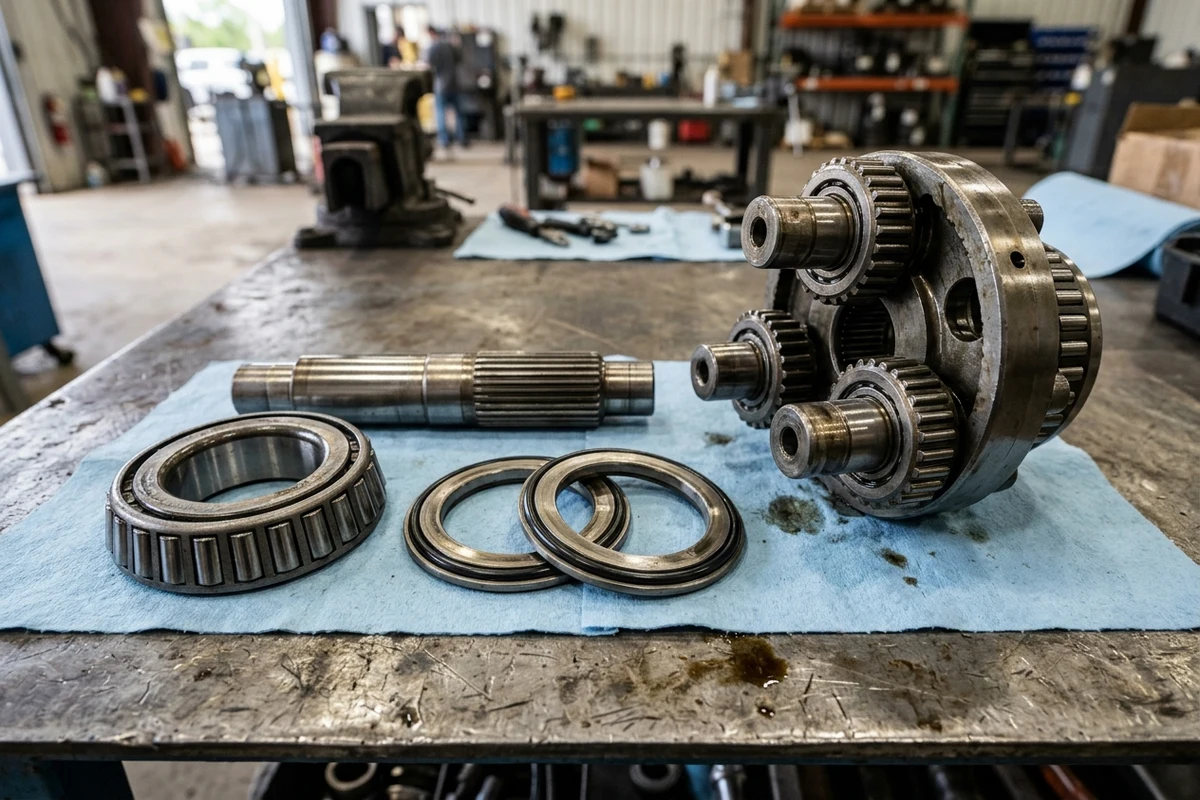
Figure 2: Inside the planetary reduction hub and seal rebuild scope—showing a Stage-2 planetary carrier with case-hardened planet gears on needle bearings, the splined sun gear input shaft, a tapered-roller main hub bearing, and the two precision-lapped alloy cast-iron Duo-Cone floating face seal rings energized by elastomeric toric O-rings.
Scroll horizontally to view all columns.
| Scope Dimension | Option 1: Complete Final Drive Assembly (Hydraulic Travel Motor + 2/3-Stage Planetary Hub) | Option 2: Planetary Reduction Gearbox Only (Ring, Sun, Planet Carriers & Floating Seal) | Option 3: Hydraulic Travel Motor Section Only (Cylinder Block, Pistons, Valve Plate, Brake Pack & Counterbalance Spool) | Option 4: Floating Duo-Cone Seal & Main Bearing Kit (Lapped Alloy Cast-Iron Rings + Toric O-Rings + Carriers) |
|---|---|---|---|---|
| Hardware Included in Quoted Price | Pre-assembled, bench-tested hydraulic travel motor, rear counterbalance/2-speed valve block, wet parking brake, AND complete 2/3-stage planetary reduction gearbox with outer cover plate | Outer ring-gear hub, cover plate, Stage 1/2/3 sun & planet gear carriers, main hub bearings, and pre-installed Duo-Cone floating seal (NO hydraulic motor or valve block) | Complete hydraulic motor housing, rear valve block (counterbalance + reliefs + 2-speed spool), rotary group, wet brake pack, and output shaft seal (NO planetary gearbox) | Matched pair of lapped 15Cr3Mo Duo-Cone seal rings + toric O-rings, main hub bearings, motor shaft seal, cover O-rings, and optional sun/planet carrier kit |
| Hardware Excluded (Must Be Reused or Ordered Separately) | Track drive sprocket (unless explicitly quoted), frame/sprocket mounting bolts (Class 10.9 / 12.9), and external hydraulic hoses | Entire hydraulic travel motor, rear valve block, wet parking brake, drive sprocket, and mounting bolts | Entire planetary reduction gearbox hub, carriers, main bearings, Duo-Cone floating seal, and drive sprocket | Main housings, hydraulic motor rotary group, counterbalance valve block, and un-ordered gear stages |
| When This Scope Is Engineeringly Sound | Default choice (85%+ of field failures): Any failure involving gear fragments, blown motor shaft seal cross-contamination, unknown prior repair history, or urgent machine-down replacement | Only when the planetary hub suffered external impact or dry-running gear failure AND the hydraulic travel motor passes bench pressure, volumetric efficiency (>= 92%), and shaft-seal tests | Only when the hydraulic motor suffered internal cavitation or valve-block failure AND the planetary gearbox oil is clean (zero metal on magnetic plug) with intact bearings and duo-cone seal | Preventative overhaul at 4,000–6,000 hours when external mud weeping begins at the Duo-Cone seal BEFORE dirt enters and destroys the main bearings or gears |
| Workshop Labor & Special Tooling Required | 2.5 to 4.5 hours bolt-on swap using a hoist, torque wrench, and case-drain pre-fill funnel (zero cleanroom teardown required) | 6 to 10 hours to unbolt motor from old hub, inspect spline/shaft seal, press/mate new gearbox, and pressure-test before track mounting | 6 to 10 hours to strip planetary carriers off old motor spindle, clean all passages, mount onto new motor, and set bearing preload | 12 to 20+ hours using a 50–100 ton hydraulic shop press, bearing induction heaters, duo-cone installation tool, and preload shimming gauges |
| Dominant Failure Mode & Prevention | Failure mode: Unflushed brass/steel swarf from the old motor's case-drain hose washing into the new unit, or > 3%–5% ratio mismatch against the opposite track. Prevention: Replace the inline case-drain filter, flush lines, pre-fill both chambers, and verify i_total and V_g on the quote. | Failure mode: Bolting a new gearbox onto an uninspected travel motor with a blown shaft seal or high case-drain pressure (> 2–3 bar), blowing out the new gearbox's Duo-Cone seal in 10–30 hours. Prevention: Bench-test motor case-drain bypass and replace the motor shaft lip seal before mating. | Failure mode: Mating a new hydraulic motor to an old planetary hub that has micro-pitted main bearings or worn sun-gear splines, snapping the new motor output shaft under shock load. Prevention: Tear down and magnaflux/inspect all planetary stages and main bearings before reuse. | Failure mode: Fingerprints, oil, or twisted toric O-rings on the lapped 15Cr3Mo Duo-Cone seal faces during installation—or reusing thinned main hub bearings that allow radial hub wobble—causing immediate gear-oil leakage. Prevention: Use a dedicated Duo-Cone installation ring tool, degrease metal seal tracks with solvent, and replace main hub bearings simultaneously. |
Engineering Rule-of-Thumb (Never Bolt a New Planetary Gearbox Onto an Uninspected Travel Motor — Case-Drain & Shaft-Seal Blowout Threshold): If a planetary reduction gearbox leaks heavy oil behind the sprocket or suffers gear failure → never install a standalone replacement Planetary Gearbox Only onto the existing hydraulic travel motor until the motor's case-drain bypass flow (Q_case <= 3% of Q_in, or <= 8–10 L/min at 34.3 MPa stall) and crankcase pressure (P_case <= 2.0 to 3.0 bar / 0.20 to 0.30 MPa) are verified on a test bench and both the high-pressure motor shaft seal and inline sintered-bronze case-drain filter are replaced, because high-pressure case-drain oil at > 2–3 bar forces ISO VG 46 hydraulic fluid past the motor shaft seal into the sealed API GL-5 gear hub, over-pressurizing the housing and blowing out the outer Duo-Cone Floating Face Seal within 10 to 30 operating hours.
3. OEM Excavator Final Drive Series & Cross-Brand Technical Baseline (6-Ton to 40-Ton Class)
Major excavator manufacturers (SANY, Komatsu, Kobelco, Hitachi, Doosan / Develon, Hyundai, Volvo, XCMG, LiuGong, Sumitomo, Case) rarely manufacture their own travel drives across all tonnage classes. Instead, they source integrated final drive assemblies from five tier-1 drivetrain manufacturers—Nabtesco (GM Series), Kayaba / KYB (MAG Series), Doosan Mottrol (TM / DM Series), Eaton (JMV Series), and Bosch Rexroth (HYDROTRAC GFT + A6VE Series)—and frequently switch suppliers across serial-number breaks on the exact same excavator model.
Scroll horizontally to view all columns.
| Excavator Tonnage Class & Representative Host Machines | Major OEM Final Drive Series (Nabtesco / KYB / Mottrol / Eaton / Rexroth) | Standard Engineering Baselines (Motor V_g, Planetary Ratio i_total, Working Pressure, Max Output Torque T_out) | Typical Hydraulic Port & Brake Configuration | Dominant Failure Mode & Prevention |
|---|---|---|---|---|
| 5–8 Ton Compact / Mini Excavator ( SANY SY55C / SY60C / SY75C, Kubota KX057 / KX080, Yanmar ViO55, Takeuchi TB260, XCMG XE60D) | • Nabtesco: GM06VN, GM07VA, GM09 / GM09VN• Kayaba ( KYB): MAG-33VP, MAG-44VP, MAG-50VP• Eaton: JMV-047, JMV-053, JMV-065• Rexroth: GFT 9 T2 / GFT 13 T2 | • Pressure: 24.5 to 31.4 MPa (245–314 bar)• Motor V_g: 33.0 to 46.6 cm3/rev (Lo) / 19.0 to 27.5 cm3/rev (Hi)• Ratio i_total: 1 : 53.0 to 1 : 75.4 (GM09)• Max Torque T_out: 6.5 to 8.83 kN*m (900 kgf*m) | 4-Port (A, B, C Drain, P_s 2-Speed) or 3-Port; compact planetary hub holds only 0.8 to 1.6 L of API GL-5 80W-90 oil | Failure mode: Rapid dry-running planetary seizure because the small 0.8–1.6 L gear oil bath boils dry after just a few days of Duo-Cone seal weeping, or clogged inline case-drain filter blowing the motor seal. Prevention: Check gear oil level every 100 hours and replace the inline bronze case-drain element at every replacement. |
| 12–15 Ton Midi Crawler Excavator ( SANY SY135C / SY155U, Komatsu PC120-6 / PC130-8, Kobelco SK135SR, Hitachi ZX130, LiuGong 915E) | • Nabtesco: GM18 / GM18VL, GM21VA, GM24VL• Kayaba ( KYB): MAG-85VP, MAG-100VP• Doosan Mottrol: TM22VC• Eaton: JMV-085, JMV-115• Rexroth: GFT 17 T2 / GFT 24 T2 | • Pressure: 31.4 to 34.8 MPa (314–348 bar)• Motor V_g: 55.8 to 88.4 cm3/rev (Lo)• Ratio i_total: 1 : 58.0 to 1 : 84.0 (GM18VL)• Max Torque T_out: 18.2 to 22.05 kN*m (1,860–2,250 kgf*m) | 4-Port (A, B SAE split flange or BSPP + C1/C2 drain + P_s 2-speed pilot); integrated Belleville wet disc brake + counterbalance spool | Failure mode: Ordering a "SY135C final drive" without checking whether the machine serial break was built with a Nabtesco GM18VL / GM21 or a KYB MAG-85VP / domestic unit with different sprocket bolt counts (12 vs. 16 holes). Prevention: Transcribe the complete stamped motor model code (e.g., GM18VL-... or MAG-85VP-...) and measure Dimensions A–E. |
| 18–25 Ton Standard Crawler Excavator ( SANY SY215C / SY235C, Kobelco SK200-8 / SK210LC, Sumitomo SH200, Doosan DX225LC, Case CX210, XCMG XE215D, LiuGong 920E) | • Kayaba (KYB): MAG-170VP (-3800G / -4000H)• Nabtesco: GM35VL, GM35VA, GM38VB / GM38VC• Doosan Mottrol: TM40VC• Eaton: JMV-155, JMV-168• Rexroth: GFT 36 T2 / GFT 45 T2 | • Pressure: 34.3 to 35.0 MPa (343–350 bar)• Motor V_g: 138.5 to 192.7 cm3/rev (Lo) / 83.9 to 118.0 cm3/rev (Hi)• Ratio i_total: 1 : 43.2 (MAG-170VP), 1 : 46.8–66.0 (GM35VL), 1 : 55.62 (GM38VB)• Max Torque T_out: 34.3 to 39.2 kN*m (3,500–4,000 kgf*m) | 4-Port (A, B high-pressure ISO 6162-2 Code 62 or large ORB/BSPP + C1/C2 case drain + P_s 2-speed shift port); gear oil fill 4.5 to 5.5 L | Failure mode: Severe bilateral tracking drift (8.3%+ speed difference) or sprocket bolt-circle mismatch when an unverified aftermarket drive (1:43.2) is bolted opposite an OEM 1:46.8 or 1:55.6 drive on a 20-ton excavator. Prevention: Verify exact nameplate suffix (-3800G vs. -4000H, -VL vs. -VB), planetary ratio i_total, and bolt counts (D & C). |
| 30–40 Ton Heavy Production Excavator ( SANY SY335C / SY365H, Kobelco SK350LC, Hyundai R335LC, Doosan DX340LC, Komatsu PC300-8 / PC360, XCMG XE370D) | • Kayaba (KYB): MAG-180VP, MAG-230VP• Nabtesco: GM60 / GM60VA, GM85• Doosan Mottrol: TM60VC• Eaton: JMV-274• Rexroth: GFT 60 T3 / GFT 80 T3 (3-Stage) | • Pressure: 34.3 to 35.0 MPa (up to 36.5 MPa peak)• Motor V_g: 180.0 to 290.7 cm3/rev (Lo) / 110.0 to 175.0 cm3/rev (Hi)• Ratio i_total: 1 : 40.47 (GM60VA) to 1 : 64.8 (MAG-180VP)• Max Torque T_out: 56.6 to 68.42 kN*m (5,770–6,977 kgf*m) | 4-Port (A, B SAE Code 62 4-bolt split flanges + C case drain + P_s 2-speed pilot); heavy 2-stage or 3-stage planetary hub holding 6.5 to 9.5 L of API GL-5 85W-140 oil | Failure mode: Stage-1/Stage-2 planetary carrier pin fatigue or tooth root bending fracture (ISO 6336) under quarry rock-ripping shock loads, or thermal breakdown of 80W-90 oil during long continuous tramming. Prevention: Specify case-hardened 18CrNiMo7-6 (HRC 58–62) OEM/Tier-1 OES planetary assemblies, fill with API GL-5 85W-140 in heavy duty, and limit continuous tramming bursts to <= 20 min with cooling pauses. |
4. Quantitative Engineering Sizing: Planetary Reduction Ratio (i_total), Output Torque (T_out), and Bilateral Speed Matching
Whenever you evaluate a replacement final drive quote—especially if an aftermarket vendor proposes a functional cross-reference for an obsolete OEM part number—verify three mathematical relationships before approving the substitute:
Equation 1: Multi-Stage Planetary Gear Reduction Ratio (i_total)
In a standard 2-stage epicyclic planetary reduction hub where each sun gear (Z_S1, Z_S2 tooth counts) drives planet gears meshing inside a stationary or coupled internal ring gear (Z_R1, Z_R2 tooth counts), the individual stage ratios (i_stage1, i_stage2) and overall mechanical reduction ratio (i_total) follow:
i_stage1 = 1 + (Z_R1 / Z_S1)
i_stage2 = 1 + (Z_R2 / Z_S2)
i_total  = i_stage1 * i_stage2 = (1 + Z_R1 / Z_S1) * (1 + Z_R2 / Z_S2)
(Note: On rotating-hub designs where the outer ring gear housing is the output member and the Stage-2 carrier is anchored to the stationary motor spindle, the exact kinematic ratio is i_total = (1 + Z_R1 / Z_S1) * (1 + Z_R2 / Z_S2) - 1, or for a 3-stage heavy excavator hub, i_total = i_stage1 * i_stage2 * i_stage3.)
- 1-Line Worked Example (
20-Ton Excavator 2-Stage Planetary Hub Ratio Verification): Given a Stage-1 sun gear withZ_S1 = 15 teeth, Stage-2 sun gear withZ_S2 = 18 teeth, and internal ring gear withZ_R1 = Z_R2 = 69 teeth(standard 1:43.2 class hubwhere Stage 1 isi_1 = 1 + 69/15 = 5.60and Stage 2 effective hub multiplier isi_2 = 7.714):i_total = 5.60 * 7.714 = 43.20 : 1 (43.20 motor shaft revolutions per 1.00 drive sprocket revolution)
Equation 2: Final Drive Output Sprocket Torque (T_out)
Combining the hydraulic travel motor's pressure differential (Delta_P in bar, where 1 MPa = 10 bar), maximum low-speed geometric displacement (V_g in cm3/rev), overall planetary gear reduction ratio (i_total), and combined hydro-mechanical efficiency (eta_mech, typically 0.86 to 0.90 across the axial-piston motor and 2-stage ISO 6336 planetary gear train), the net output torque delivered to the track drive sprocket (T_out in N*m) is:
T_out [N*m] = (Delta_P [bar] * V_g [cm3/rev] * i_total * eta_mech) / (20 * pi)
- 1-Line Worked Example (
21-Ton Excavator KYB MAG-170VP Class Output Torque in Low vs. High Speed): Assuming working relief differentialDelta_P = 343 bar(34.3 MPa), low-speed motor displacementV_g,Lo = 175.0 cm3/rev(high-speed displacement V_g,Hi = 108.0 cm3/rev), planetary reduction ratioi_total = 43.20, and hydro-mechanical efficiencyeta_mech = 0.89(20 * pi = 62.8318):Low-Speed Mode (Turtle): T_out,Lo = (343 * 175.0 * 43.20 * 0.89) / 62.8318 = 36,725 N*m (36.73 kN*m) High-Speed Mode (Rabbit): T_out,Hi = (343 * 108.0 * 43.20 * 0.89) / 62.8318 = 22,664 N*m (22.66 kN*m)
Equation 3: Bilateral Track Speed Mismatch (Delta_v_track) & Case-Drain Bypass Limit (Q_case,max)
When main pump flow Q_in (L/min) is split equally to the left (LH) and right (RH) travel motors (with motor volumetric efficiency eta_vol approx 0.94), the sprocket rotational speed n_sprocket (rpm), bilateral track speed mismatch Delta_v_track (%), and maximum allowable motor case-drain bypass flow Q_case,max (L/min) are governed by:
n_sprocket [rpm]    = (Q_in [L/min] * 1000 * eta_vol) / (V_g [cm3/rev] * i_total)
Delta_v_track [%]   = ( |n_sprocket,RH - n_sprocket,LH| / n_sprocket,LH ) * 100%
Q_case,max [L/min]  = 0.05 * Q_in  (Rebuild threshold; healthy new/reman motor <= 0.02 to 0.03 * Q_in at P_case <= 2.0-3.0 bar)
- 1-Line Worked Example (
Why Bolting a 1:43.2 Drive Opposite a 1:46.8 Drive Causes Severe Tracking Drift): Suppose a 21-ton excavator deliversQ_in = 210 L/min(eta_vol = 0.94,V_g = 170.0 cm3/rev) to both tracks, where the original Left final drive hasi_total,LH = 46.80and an unverified Right replacement drive hasi_total,RH = 43.20:n_sprocket,LH = (210 * 1000 * 0.94) / (170.0 * 46.80) = 24.81 rpm vs. n_sprocket,RH = (210 * 1000 * 0.94) / (170.0 * 43.20) = 26.88 rpm --> Delta_v_track = ((26.88 - 24.81) / 24.81) * 100% = +8.34% speed mismatch (16.7 m drift per 200 m travel; max healthy Q_case <= 0.03 * 210 = 6.3 L/min)
Engineering Rule-of-Thumb (Single-Side Replacement Planetary Reduction Ratio i_total & Displacement V_g Bilateral Speed-Match Threshold): If replacing only one final drive (Left or Right) on a crawler excavator → verify before ordering that the replacement unit's overall planetary reduction ratio (i_total = i_stage1 * i_stage2) and 2-speed hydraulic motor displacements (V_g,Lo / V_g,Hi) match the opposite track's drive within <= 2.0% (never > 3.0%–5.0%), because installing a 1:43.2 aftermarket drive opposite an OEM 1:46.8 drive creates an 8.34% bilateral track speed differential that forces continuous steering corrections, overheats the main hydraulic circuit, and accelerates single-side track link, roller flange, and drive sprocket tooth wear.
5. Pre-Order Mechanical Metrology (Dimensions A, B, C, D, E) & Hydraulic Port Verification
When a final drive nameplate has been ground off by quarry rock or painted over during a previous rebuild, never guess fitment from the excavator model decal alone. Measure the five standardized mechanical interface coordinates (A, B, C, D, E) in millimeters (mm) plus the rear hydraulic port arrangement:
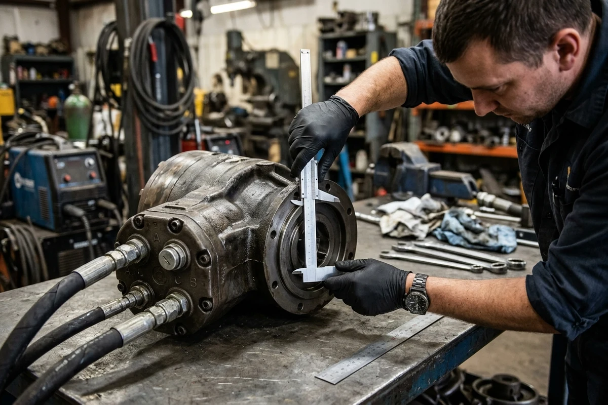
Figure 3: Pre-order final drive interface metrology—measuring the mounting flange pilot diameter (Dimension A / B) and bolt circle diameter (BCD) with a vernier caliper while verifying the rear hydraulic port layout (Main A/B, Case Drain C, and 2-Speed Pilot).
Scroll horizontally to view all columns.
| Metrology Coordinate / Interface | Exact Feature to Measure (in mm) | How to Measure Accurately in the Workshop | Why Model-Only Lookup Fails Without This Measurement | Dominant Failure Mode & Prevention |
|---|---|---|---|---|
Dimension A: Drive-Sprocket Hub Pilot Diameter (OD_pilot,sprocket) | Outside diameter (mm) of the machined circular shoulder on the rotating planetary hub where the center bore of the track drive sprocket registers | Clamp a large vernier caliper across the raised circular spigot on the sprocket mounting face (or measure the inside diameter ID of the removed steel drive sprocket center hole) | A 2 mm pilot mismatch (e.g., 260.0 mm vs. 262.0 mm) either prevents the sprocket from sliding onto the hub or leaves radial play that shears the sprocket bolts under load | Failure mode: Sprocket mounts eccentrically with radial clearance, shearing 15 to 20 Class 10.9 sprocket bolts during reverse rock travel. Prevention: Record Dimension A (mm) to +/- 0.2 mm precision. |
Dimension B: Track-Frame Mounting Pilot Diameter (OD_pilot,frame) | Outside diameter (mm) of the stationary rear flange spigot on the travel motor housing that inserts into the machined center bore of the excavator track frame | Measure across the circular register shoulder on the inboard (motor) side of the chassis mounting flange using outside calipers or a steel millimeter rule | OEMs frequently machine different track-frame pilot bores (e.g., 270 mm vs. 285 mm) when switching between Nabtesco GM and Kayaba MAG suppliers on the same excavator model | Failure mode: Replacement final drive housing will not enter the excavator track frame bore during field installation. Prevention: Measure Dimension B (mm) on the removed drive or inside the track-frame bore. |
Dimension C: Sprocket Bolt Circle Diameter (BCD_sprocket) & Hole Count | Center-to-center diameter (mm) across two opposite threaded sprocket mounting holes + total hole count (e.g., 12, 15, 16, 18, 20, or 24 holes) + thread size (e.g., M16x2.0, M20x2.5) | Measure from the left edge of one bolt hole to the left edge of the directly opposite bolt hole (for an even number of holes) and count every threaded hole around the rotating hub | On 20-ton excavators (SY215C, SK200, DX225), some serial ranges use a 15-hole or 16-hole sprocket while later serials use an 18-hole or 20-hole sprocket on the same track chain pitch | Failure mode: Receiving a final drive with 16 sprocket holes when your excavator sprocket has 18 bolt holes, forcing an unscheduled sprocket purchase and delay. Prevention: Count sprocket holes and measure Dimension C (mm). |
Dimension D: Track-Frame Bolt Circle Diameter (BCD_frame) & Hole Count | Center-to-center diameter (mm) across two opposite chassis mounting bolt holes + total hole count (e.g., 12, 16, 18, 20, or 24 holes) + bolt diameter/thread | Measure center-to-center across opposite holes on the stationary frame flange and count all mounting holes (noting any asymmetrical dowel-pin holes or skipped bolt positions) | Frame bolt patterns vary between standard-undercarriage (STD) and long/heavy-duty undercarriage (LC / HD) variants of the same excavator model | Failure mode: Chassis mounting flange bolt holes do not align with the welded track-frame bolt ring. Prevention: Record exact hole count, thread size, and Dimension D (mm). |
Dimension E: Sprocket Mounting Face Axial Offset Depth (L_offset) | Perpendicular axial distance (mm) from the flat track-frame mounting flange surface to the flat drive-sprocket mounting surface | Lay a rigid steel straightedge across the sprocket mounting face and measure perpendicular depth down to the frame mounting flange face with a depth bar or steel rule | If axial offset E is off by >= 8–15 mm, the bolted drive sprocket sits inboard or outboard of the track roller and front idler centerline | Failure mode: Misaligned drive sprocketchews into the inner side faces of the excavator track links and derails the track chain on slopes. Prevention: Measure Dimension E (mm) before ordering. |
Hydraulic Port Count & Thread / Flange Standard (3-Hose vs. 4-Hose) | Count active rear ports: Main High-Pressure A & B, Case Drain C1 / C2 (one active, one plugged), and 2-Speed Shift Pilot P_s (plus brake release port b on skid-steer/CTL drives) | Tag and photograph all hoses before disconnection; measure port thread ID/OD or ISO 6162 4-bolt split-flange spacing with calipers using our part photo checklist | Single-speed Motors (3 hoses: A, B, Drain) and Dual-Speed Motors (4 hoses: A, B, Drain, 2-Speed Pilot) share identical external housings on many GM and MAG models | Failure mode: Ordering a 3-port motor for a 4-hose 2-speed machine, losing high-speed travel (Rabbit mode), or encountering BSPP (G) vs. Metric / ORB fitting leaks. Prevention: Specify 3-port vs. 4-port and send a perpendicular photo of the rear valve block. |
Engineering Rule-of-Thumb (5-Coordinate Frame/Sprocket Caliper Metrology A/B/C/D/E + 3-Hose vs. 4-Hose Port Count Threshold Before Ordering): If ordering a replacement final drive for a 13-ton to 36-ton crawler excavator (SANY SY135C / SY215C / SY335C, Kobelco SK200, Doosan DX225LC, Komatsu PC200-8, XCMG XE215D) where OEMs dual-source between Kayaba MAG-170VP / MAG-180VP, Nabtesco GM18VL / GM35VL / GM38VB / GM60VA, Doosan Mottrol TM22VC / TM40VC / TM60VC, and Eaton JMV-155 across serial breaks → measure both the track-frame pilot OD (B) and bolt count/BCD (D) AND the drive-sprocket pilot OD (A), bolt count/BCD (C), and axial offset (E), plus the active hydraulic hose count (3-hose vs. 4-hose 2-speed pilot) before releasing payment, because 20-ton class final drives share nearly identical outer shell diameters while machining incompatible 15-bolt vs. 18-bolt sprocket hubs and 16-bolt vs. 20-bolt frame flanges that prevent installation on site.
Engineering Rule-of-Thumb (Planetary Gear Oil API GL-5 80W-90 50–100 Hour Break-In Drain & 1,000 Hour Routine Service Threshold): When commissioning any replacement excavator final drive or rebuilt planetary gearbox → rotate the outer hub until the oil fill plug is at 12 o'clock and the level check plug is at horizontal 3 o'clock or 9 o'clock (50% hub volume, 2.5 to 9.5 L), fill with extreme-pressure API GL-5 SAE 80W-90 (or 85W-140) gear oil (never shipping dry—many air-freighted drives ship drained), pre-fill the hydraulic travel motor crankcase via its upper C1/C2 drain port with ISO 4406 <= 18/16/13 ISO VG 46 hydraulic fluid, and perform the mandatory first gear-oil break-in drain at 50 to 100 operating hours (followed by level/magnetic-plug checks every 100 to 250 hours and full drains every 500 to 1,000 hours), because initial ISO 6336 gear-tooth running-in sheds microscopic steel particles that pit planetary needle bearings and score lapped 15Cr3Mo duo-cone seal rings if left circulating past 100 hours.
6. 5-Year Excavator Final Drive Supply-Scope, Cross-Contamination & Ratio-Mismatch TCO Ledger
Choosing the wrong replacement scope (Gearbox Only on a bypassing motor) or skipping Dimensions A–E and ratio (i_total) verification turns a straightforward half-day bolt-on swap into tens of thousands of dollars in repeat failures and undercarriage destruction:
Scroll horizontally to view all columns.
| 5-Year Final Drive TCO Cost Driver | Unverified Scope / Partial Sub-Assembly Guesswork | Verified Complete Scope + A–E Metrology + ISO 4406 / GL-5 Protocol | 5-Year Financial & Operational Impact (Per Excavator) | Dominant Failure Mode & Prevention |
|---|---|---|---|---|
1. Cross-Chamber Contamination Repeat Failure (Gearbox Only on Uninspected Motor) | Bolting a $1,400 standalone planetary gearbox onto an old travel motor with a worn shaft seal or plugged case-drain filter (> 2–3 bar) | Bench-tested Complete Final Drive Assembly (Motor + Gearbox) + new sintered-bronze inline case-drain filter ($45) + flushed drain line | Prevents $4,200–$8,500 in repeat gearbox/seal blowouts and 3–5 days of secondary machine downtime ($1,200–$2,000/day) | Failure mode: Pressurized ISO VG 46 case-drain oil blows past the old motor shaft seal into the new planetary hub, popping the outer Duo-Cone floating seal in 10–30 hours. Prevention: Replace the complete assembly or pressure-test motor case-drain bypass (<= 2.0 bar) and replace the inline case-drain filter. |
2. Bilateral Ratio Mismatch (i_total) & Undercarriage Flange Wear | Installing an unverified aftermarket final drive (e.g., 1:43.2) opposite an OEM drive (1:46.8 or 1:55.6) when replacing a single side | Exact nameplate code & planetary ratio i_total verification (<= 2% bilateral speed difference) before dispatch | Saves $5,500–$11,000 in premature single-side track chain, track roller flange, front idler, and sprocket tooth wear over 5 years | Failure mode: 8.3%+ speed mismatch forces the excavator to crab sideways ("dog-walk"), grinding track link side rails against roller flanges and overheating hydraulic oil. Prevention: Lock i_total and V_g against the opposite track's final drive tag. |
3. Heavy Air-Freight Fitment Returns (Dimensions A–E & Bolt Count Collisions) | Ordering by machine model decal alone ("SY215C" or "SK200") and receiving a 16-hole sprocket hub instead of an 18-hole hub | Pre-shipment caliper verification of Dimensions A, B, C, D, E (mm), bolt hole counts, and 3-hose vs. 4-hose port layout (ISO 2859-1 Ac = 0) | Avoids $1,800–$4,200 in two-way international air freight on 180–420 kg cast-steel final drives plus 15% restocking fees and 10–14 days lost work | Failure mode: 280 kg final drive arrives on site and cannot bolt to the track frame (Dimension D) or drive sprocket (Dimension C). Prevention: Submit the completed 5-dimension (A–E) worksheet and tag photos before shipment release. |
4. Dry-Start Motor Seizure & Un-Drained 50–100 h Break-In Gear Oil | Bolting on a replacement drive and tramming immediately without checking GL-5 gear oil level or pre-filling the motor case-drain cavity | Mandatory pre-startup 3/9 o'clock API GL-5 80W-90 fill check + ISO VG 46 (<= 18/16/13) motor case pre-fill + 50–100 h break-in oil drain | Doubles planetary carrier and Duo-Cone seal service life from 2,500 hours to 6,000–8,000+ hours (saving 1–2 full replacements over 5 years) | Failure mode: < 30 second dry friction welding of motor brass piston slippers on initial startup, or 50-hour break-in steel filings pitting Stage-2 needle bearings. Prevention: Pre-fill motor case drain, verify GL-5 gear oil level prior to first movement, and drain gear oil at 50–100 hours. |
| 5. Companion Drive Sprocket, Bolt & Filter Consolidation | Reusing hooked/worn drive sprocket teeth and stretched mounting bolts on a brand-new final drive hub | Consolidating a new hardened drive sprocket (HRC 52–56), Class 10.9 / 12.9 flange bolts, and inline hydraulic filters in one crate | Eliminates $1,200–$3,000 in accelerated track bushing wear and prevents sheared sprocket bolts under high-torque reverse digging | Failure mode: Worn sprocket teeth climb the track chain bushings, or reused stretched bolts loosen and ovalize the new planetary hub's threaded holes. Prevention: Bundle companion undercarriage parts, seal kits, and filters using our multi-brand parts list guide. |
7. Frequently Asked Questions About Excavator Final Drives & Replacement Quotes
What is the difference between an excavator final drive and a travel motor?
In field terminology, operators often call the entire track drive unit a "final drive" or a "travel motor." In strict mechanical engineering and parts cataloging, they are the two bolted halves of the complete track drive assembly:
- The Hydraulic Travel Motor (
inboard line side) is the high-pressure fluid-power component (swashplate axial-piston rotary group + counterbalance brake valve + 2-speed shift spool + wet multi-disc parking brake) lubricated by thinISO VG 46hydraulic oil circulating from the main pump. - The Planetary Reduction Gearbox (
outboard sprocket side, technically the final drive reducer) is the mechanical torque-multiplying gear hub (2-stage or 3-stage sun, planet, and ring gears + main bearings + Duo-Cone floating face seal) lubricated by thickAPI GL-5 SAE 80W-90 / 85W-140gear oil. When comparing two quotes, always verify in writing whether the price covers Option 1 (Complete Bolted Assembly: Motor + Gearbox), Option 2 (Planetary Gearbox Only), or Option 3 (Hydraulic Travel Motor Only).
Why did my new planetary gearbox blow its outer Duo-Cone floating seal after only 20 hours?
A brand-new planetary gearbox (Option 2) almost never blows its outer Duo-Cone floating seal at 10 to 30 hours due to a defective seal. Instead, the failure is caused by high-pressure hydraulic cross-contamination from the hydraulic travel motor:
- Either the existing travel motor's internal piston-to-barrel wear or a plugged inline sintered-bronze case-drain filter caused motor crankcase pressure (
P_case) to spike above2.0 to 3.0 bar(30 to 45 psi), - That back-pressure ruptured the motor output shaft lip seal that separates the hydraulic motor from the planetary gearbox, and
- Pressurized
ISO VG 46hydraulic fluid pumped straight into the sealed planetary hub, completely filling its expansion airspace and forcing the lapped15Cr3MoDuo-Cone floating seal rings apart behind the sprocket. Always test case-drain pressure/flow and replace the inline case-drain filter before installing any replacement drive.
Can I replace just one final drive on my excavator, or will the machine track crooked?
You can replace a single side (Left or Right) only if you verify that the replacement assembly's overall planetary reduction ratio (i_total) and hydraulic motor geometric displacement (V_g,Lo / V_g,Hi) match the drive installed on the opposite track within <= 2.0%. On 20-ton class excavators (such as SANY SY215C, Kobelco SK200, or Doosan DX225LC), OEMs use Kayaba MAG-170VP (i_total = 1:43.2), Nabtesco GM35VL (i_total = 1:46.8 to 1:66.0), and Nabtesco GM38VB (i_total = 1:55.62). Bolting a generic aftermarket drive with a 1:43.2 ratio opposite an existing 1:46.8 drive creates an 8.34% speed mismatch, causing the excavator to pull continuously toward the slower track.
Are Left (LH) and Right (RH) excavator final drives interchangeable?
Mechanically, the complete final drive assembly (hydraulic travel motor + planetary reduction gearbox) is symmetrical (bi-directional) on almost all crawler excavators—the same part number mounts on either the Left (LH) or Right (RH) track frame because reversing hoses A and B reverses rotation, and the rear counterbalance valve operates symmetrically in both directions. However, you should still record Left or Right position on your quote request for two practical reasons:
- If the planetary gear hub arrives pre-serviced or has angled drain/level plugs or hose adapter elbows pre-fitted, port orientation relative to the track-frame access cover depends on which side it mounts, and
- Recording which side failed (
LHvs.RH) allows your fleet maintenance log and our engineering team to check whether the opposite side was previously replaced with a different sub-supplier revision.
What to Send Us Before Approving a Final Drive Replacement
When you are ready to compare quotes or source a complete final drive, travel motor, planetary gearbox, or Duo-Cone seal kit via our Request a Quote page, send the five records below so our team can verify exact mechanical and hydraulic fitment before dispatch:
Scroll horizontally to view all columns.
| Information to Provide | Why It Locks Fitment & Scope | Related HeavyPartsSource Guides & Categories |
|---|---|---|
1. Travel Drive Nameplate Photo (10–25 deg Raking Light) + Machine 17-Char PIN (ISO 10261) | Identifies the exact OEM assembly (Nabtesco GM35VL, KYB MAG-170VP, Mottrol TM40VC, Eaton JMV, Rexroth GFT), suffix code, and serial break | How to Photograph a Part · Find an Excavator Part Number |
2. Target Supply-Scope Selection (Option 1, 2, 3, or 4) + Sprocket Inclusion | Confirms whether your quote covers the Complete Assembly (Motor + Gearbox), Gearbox Only, Motor Only, or Duo-Cone Seal/Bearing Kit, and whether a new drive sprocket is included | Final Drives Category · Travel Motors Category · Undercarriage Parts |
3. 5-Coordinate Caliper Metrology (Dimensions A, B, C, D, E in mm) & Bolt Counts | Guarantees physical fit into your excavator track frame (Pilot B, BCD D, hole count) and onto your drive sprocket (Pilot A, BCD C, hole count, Offset E) | Excavator Track Chain Fitment Checklist · Quality Checks |
4. Rear Hydraulic Port Count (3-Hose vs. 4-Hose 2-Speed) & Prior Failure Mode | Prevents shipping a 1-speed motor for a 2-speed harness and flags whether swarf flushing and inline case-drain filters are required | Replacement Hydraulic Pump Guide · Hydraulic Cylinder Seal Kits |
| 5. Opposite-Side Final Drive Tag (When Replacing Only One Side) | Confirms bilateral planetary reduction ratio (i_total) and motor displacement (V_g) compatibility so the excavator tracks straight | Sourcing and Quotation Process · Multi-Brand Parts List Guide |
Copy the Excavator Final Drive Scope & A–E Metrology Worksheet
Copy the editable worksheet below, fill in the known fields from your removed final drive and machine serial plate, and leave any unmeasured field marked as Unknown — verify before ordering. Paste the completed worksheet into our quote request form along with your nameplate and port photos, or explore our final drives, travel motors, swing motors, undercarriage parts, and part identification service.
Method and Sources
This engineering guide and supply-scope verification matrix were compiled and verified in October 2026 by the HeavyPartsSource drivetrain and hydraulic engineering team using international gear, spline, and fluid-power standards alongside OEM excavator final drive documentation:
- ISO 6336-1 / ISO 6336-2 / ISO 6336-3 — Calculation of load capacity of spur and helical gears (contact stress / macropitting resistance and tooth-root bending strength baselines for multi-stage epicyclic planetary reduction gear sets) (
oem-excavator-final-drive-specs-and-standards.md). - Nabtesco (
GM09,GM18VL,GM35VL,GM38VB,GM60VA), Kayaba / KYB (MAG-85VP,MAG-170VP,MAG-180VP), Doosan Mottrol (TM22VC,TM40VC,TM60VC), Eaton (JMV-047,JMV-155), and Bosch Rexroth (HYDROTRAC GFT+A6VE) Technical Reference Data — Nominal working pressures (31.4 to 36.5 MPa), dual-speed swashplate displacements (V_g,Lo / V_g,Hi), planetary reduction ratios (1:40.47to1:84.0), and maximum output sprocket torques (8.83 to 68.42 kN*m) (tfdrive-nabtesco-gm-series-guide.txt,oem-excavator-final-drive-specs-and-standards.md). - Bosch Rexroth Axial Piston Commissioning Manual (
RA-A 92703/12.11) & ISO 4406:2021 Hydraulic Cleanliness Baselines — Axial-piston rotary group running clearances (2–5 um), fluid cleanliness (ISO 4406 <= 18/16/13), maximum allowable crankcase drain pressure (P_case <= 2.0–3.0 bar), and mandatory housing pre-fill procedures (rexroth-axial-piston-commissioning-manual.txt,axial-piston-pump-iso-4406-contamination.md). - Texas Final Drive (
Jim Strong, Terminology for Final Drive Motors, Part 1 & What to Know Before You Order a Final Drive) & Mecatra A/S (What Is the Difference Between a Final Drive and a Travel Motor? & How to Measure a Final Drive Correctly) — Hydraulic hub versus planetary hub nomenclature,A/Bflow/return andC1/C2case-drain port layouts, Belleville wet multi-disc brake stacks,API GL-5 SAE 80W-90versusISO VG 46dual-chamber fluid isolation, and 5-coordinate caliper metrology (Dimensions A, B, C, D, E) (texas-final-drive-terminology-part1.txt,texas-final-drive-order-checklist.txt,mecatra-final-drive-vs-travel-motor.txt,mecatra-how-to-measure-final-drive.txt). - DIN 5480 / JIS B 1603 (Involute Splines), ASTM A532 / 15Cr3Mo (Duo-Cone Floating Face Seal Metallurgy), and ISO 10261:2021 (Earth-Moving Machinery — 17-Character Product Identification Numbering System) — Motor-to-sun-gear spline interfaces, lapped alloy cast-iron floating seal rings, and machine PIN serial-break verification (
din-5480-eassistant.md,iso-10261-preview.txt).