
Publisher: HeavyPartsSource
An excavator track chain (track link assembly) is an articulated forged-steel pin-and-bushing loop whose replacement fitment is defined by six physical coordinates: (1) nominal 4-link pitch (135 to 260 mm), (2) total link count per side (37L to 53L+ across STD, LC, NLC, or SLR undercarriage frames), (3) track shoe 4-bolt hole spacing (transverse D/E x longitudinal B) and high-tensile bolt diameter (M12 to M27), (4) bushing outer diameter (D_b) and pin diameter (d_pin), (5) inner/outer link rail width (W_rail) and rail height (H_link), and (6) joint sealing and master link architecture (Sealed & Greased Polyurethane vs Dry vs Oil SALT, and Press-Fit Master Pin vs Split Alligator Master Link). Because heavy-equipment manufacturers build the same excavator model with multiple frame lengths and bolt grids, ordering a replacement track chain by machine tonnage, cab decal alone, or rough tape length causes $2,800 to $9,500 in wrong-part freight returns, un-tensionable track loops (45L STD vs 49L LC frame collisions), misaligned track shoe bolt holes (M18 vs M20), premature bushing failure within 200 operating hours on hooked drive sprockets, and unplanned machine downtime.
To eliminate fitment errors across Caterpillar, Komatsu, SANY, Hitachi, Kobelco, Doosan/Develon, Hyundai, Volvo, and Berco/ITM/ITR interchange systems, use the 6-Dimension Excavator Track Chain Fitment Verification Matrix below alongside your machine's ISO 10261:2021 17-character Product Identification Number (PIN) and stamped link forging number:
Scroll horizontally to view all columns.
| Fitment Coordinate / Scope Layer | How to Measure or Transcribe on the Machine | Governing Standard / OEM Baseline | Dominant Failure Mode & Prevention |
|---|---|---|---|
1. Nominal Track Link Pitch (P_nom = L_4-link / 4) | Pull chain taut in forward travel; measure center-to-center across 4 consecutive link pitches (Pin 1 to Pin 5) and divide by 4 | Standard excavator nominal pitches: 135.0 mm, 154.0 mm, 171.45 mm / 175.0 mm, 190.0 mm, 203.2 mm, 215.9 mm / 216.0 mm, 228.6 mm, 260.0 mm | Failure mode: Measuring a single worn link includes 2.5–4.5 mm of internal pin/bushing clearance, over-reading a 190.0 mm chain as 194 mm or a 171.45 mm chain as 175.0 mm. Prevention: Always measure across 4 link pitches (4 * P_nom = 760.0 mm for 190 mm) and divide by 4. |
2. Total Link Count (N_links) & Frame Code (STD vs. LC / SLR) | Chalk-mark the master link (split or chamfered pin) and physically count every link pitch section (N_links) around one full loop | ISO 10261:2021 17-char PIN + frame suffix (STD, LC, NLC, SLR, HD); typical 20-ton class: 45L (STD), 46L, 49L (LC), or 51L–52L (SLR) | Failure mode: Ordering by "CAT 320" or "PC200" model decal and receiving a 45-link STD chain for a 49-link LC frame (760 mm too short to close around the front idler). Prevention: Physically count every link section twice and record the machine PIN. |
3. Track Shoe 4-Bolt Pattern (D, E, B) & Bolt Size (L) | Measure inner transverse spacing E (mm), outer transverse spacing D (mm), longitudinal spacing B (mm), and bolt shank OD L | ISO 898-1 Property Class 12.9 fine-thread plow bolts (M14x1.5, M16x1.5, M18x1.5, M20x1.5, M22x1.5, M24x1.5/2.0); 20-ton 190 mm baseline: D=160 mm, E=125 mm, B=65 mm, M20 | Failure mode: Existing triple-grouser track shoes will not bolt onto the new link assembly because of an M18 vs. M20 hole mismatch or 125/160 mm gauge shift across sub-series (PC200-3 KM1170 vs. PC200-6 KM782). Prevention: Measure D, E, B (+/- 0.5 mm) and bolt thread diameter with calipers. |
4. Bushing OD (D_b), Pin OD (d_pin) & Rail Width (W_rail) | Clamp vernier calipers across the unworn end of the track bushing (D_b), pin boss (d_pin), inner rail gap (W_rail,in), and link height (H_link) | ISO 683-1 forged 35MnB links (HRC 52–58 rail) + 20CrMnTi carburized bushings (HRC 58–62); 20-ton 190 mm baseline: D_b = 59.3 mm, d_pin = 38.2 mm, H_link = 104–105 mm | Failure mode: Heavy-Duty (HD / EWL) oversized bushing (e.g., 62.0 mm vs. 59.3 mm) jams inside standard sprocket tooth roots, or narrow inner rail width (W_rail,in) binds on bottom roller center flanges. Prevention: Verify stamped link forging number (e.g., CR5350, KM782, 20Y-32-00014) and caliper dimensions. |
| 5. Joint Sealing & Master Link Architecture | Inspect link counterbore for polyurethane W-seal (Greased), oil plug (SALT), or open joint (Dry), and identify Master Pin vs. Split Master Link | Excavator standard: Sealed & Greased (Polyurethane Seal + EP Grease) with press-fit/Easy-Fit master pin; Dozer/Mining: Vacuum Oil-Filled SALT with Split Alligator Master Link | Failure mode: Shipping a press-fit regular master pin chain to a remote jobsite that lacks a 100-ton portable hydraulic track pin press, or using a split master link without matching master shoe bolt length. Prevention: Specify master joint type (Press-Fit Pin, Easy-Fit Collar Pin, or Split Master Link) on the quote. |
6. Quoted Supply-Scope Envelope (ISO 8000-110 UOM) | Separate Bare Track Link Assembly (Chain Only) from Pre-Bolted Complete Track Group (Chain + Shoes + Class 12.9 Bolts) and companion parts | ISO 8000-110 UOM (Piece vs. Bare Chain ASSY vs. Complete Track Group); HeavyPartsSource undercarriage parts line-item protocol | Failure mode: Assuming a quote for "2x Track Chains" includes triple-grouser track shoes, 360–400x Class 12.9 bolts/nuts, and drive sprockets. Prevention: List chains, shoes, bolts, sprockets, rollers, and idlers on separate itemized lines. |
1. Six Mandatory Metrology Coordinates: Why Machine Tonnage and Rough Length Fail
When an excavator operator or fleet buyer searches "what excavator track chain do I need", the most common—and most expensive—procurement mistake is assuming that all excavators in the same tonnage class (e.g., "20-ton excavator" or "CAT 320 / Komatsu PC200 / SANY SY215") share an identical track chain. In heavy-equipment undercarriage engineering, machine tonnage only places a crawler within a general pitch family; it never locks physical interchangeability:
- Undercarriage Frame Length Variants (
STDvs.LCvs.NLCvs.SLR) Change Link Count (N_links) on the Exact Same Excavator Model: A 20-ton class crawler excavator running a190.0 mmnominal pitch link assembly is factory-built in multiple track-frame lengths. A Standard (STD) undercarriage on aCAT 320orKomatsu PC200-6/7/8uses45 linksper side (unrolled new length = 45 * 190.0 mm = 8,550 mm). A medium frame (Hitachi EX200-3orKomatsu PC200-3) uses46 linksper side (8,740 mm). A Long Crawler (LC) frame (SANY SY215C,Kobelco SK200-8,Hyundai R210-7,Komatsu PC200LC,CAT 320L / 225D) uses49 linksper side (9,310 mm—exactly760 mmlonger than the45-linkchain). Super Long Reach (SLR) and low-ground-pressure swamp frames use51 to 54 linksper side. - Internal Pin-to-Bushing Wear Elongates the Old Chain by
120 to 180+ mm(+2.5 to +4.0 mmper Link): As abrasive silica dust penetrates the pin-to-bushing interface over3,500 to 5,000 operating hours, every joint wears radially. Measuring a single worn link center-to-center (1-pitch reading) or measuring the total unrolled length of a stretched chain laid on the shop floor embeds that cumulative wear into your dimension. A worn171.45 mm(6.75 in) chain stretched by+3.5 mm/linkmeasures175.0 mmper link—matching the nominal pitch of an entirely different175.0 mm(Komatsu PC100-5 / Hitachi EX200-1) chain whose bushings will jam on a171.45 mmdrive sprocket within half a revolution. - Sub-Series revisions Shift Track Shoe Bolt Diameters (
M18vs.M20vs.M22) and Bolt-Hole Gauges (D x E x B): Even when both nominal pitch (190.0 mm) and link count (45Lor46L) match, OEMs revise the forged link's top mounting pad across series breaks. For example, aKomatsu PC200-3(Berco KM1170) uses an18.3 mm(M18 x 1.5) track shoe bolt hole, whereas aKomatsu PC200-5/6/7/8(Berco KM782, OEM20Y-32-00014),CAT 320(Berco CR5350, OEM9W9354), andSANY SY215Cuse a20.3 mm(M20 x 1.5) bolt hole. If you order a bare track chain intending to transfer your existing600 mmtriple-grouser shoes, an unverified bolt-hole or gauge shift stops assembly cold.
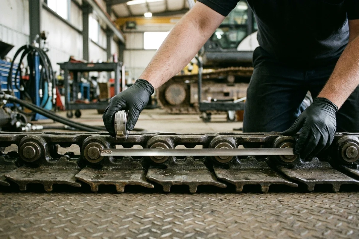
Figure 1: Measuring true nominal track chain pitch and internal pin-and-bushing elongation across four consecutive link pitches (Pin 1 center to Pin 5 center = 4 * P_nom) along a taut section of the articulated forged-steel track link assembly.
Step-by-Step Field Metrology Protocol (Coordinates 1 to 6)
Before submitting a request through our undercarriage parts catalog or quote request form, record these six physical measurements in millimeters (mm):
- Coordinate 1 — 4-Link Pitch Span (
L_4-linkinmm->P_nom = L_4-link / 4): Roll the excavator forward1 to 2 meterson level ground and let it coast to a stop without braking so the upper and lower track spans are pulled taut in forward drive contact (eliminating slack between pins and bushings). Using a rigid steel millimeter tape measure, hook or align the zero mark on the exact center (or left outer edge) of Pin 1, count four complete link sections (skipping Pins 2, 3, and 4), and read the distance to the exact same reference point (center or left outer edge) on Pin 5. Divide that4-linkmeasurement by4(or if measuring from Pin 1 to Pin 4 across3 link sections, divide by3) and match it against the standard nominal pitch baseline (135.0 mm,154.0 mm,171.45 mm,175.0 mm,190.0 mm,203.2 mm,215.9 mm,228.6 mm,260.0 mm). - Coordinate 2 — Total Link / Pitch Section Count (
N_linksper Side): Locate the Master Pin / Master Link (identifiable by a recessed center dimple, chamfered pin ends, locking collar, or diagonal split across the link forging) and mark it with high-visibility paint or soapstone chalk (Link #1). Walk around the entire perimeter of the track—over the carrier rollers, around the front idler, under the bottom track rollers, and around the final drive sprocket—marking every 5th link (#5, #10, #15...) until you return toLink #1. Never count only the top half and multiply by two; always count every single pitch section (e.g., 45L, 46L, 47L, 48L, 49L, 51L). - Coordinate 3 — Forged Link Stamped Casting / Part Number (
OEM / Berco / ITM Code): Wire-brush the recessed web on the side of two or three standard links and the master link. Photograph the raised forging characters under10 to 25 degraking light following our part photography guide. A single stamped forging code—such asCR5350,KM782,KM959,KM2233,20Y-32-00110, or9W9354—immediately locks the link geometry, rail height, and shoe bolt pattern. - Coordinate 4 — Bushing Outer Diameter (
D_b) & Pin Diameter (d_pin): Using a stainless vernier caliper (+/- 0.1 mm) or ultrasonic undercarriage gauge, measure the Track Bushing OD (D_b) at the unworn outer edge next to the link boss (away from the center sprocket-contact zone) and measure the Track Pin OD (d_pin) where visible at the master pin or outer link boss. On a standard190.0 mmpitch 20-ton excavator chain (Komatsu 20Y-32-00014 / CAT 320 / SANY SY215C), new standard values areD_b = 59.3 mmandd_pin = 38.2 mm. - Coordinate 5 — Inner & Outer Link Rail Width (
W_rail,in/W_rail,out) & Link Height (H_link): Measure the inside clearance width (W_rail,in) between the left-hand and right-hand forged links where the center guide flanges of the bottom rollers and front idler ride (typically 80 to 86 mmon190 mmpitch), the outside width across both link rails (W_rail,out,typically 164 to 170 mm), and the vertical Link Height (H_link) from the flat shoe-bolting surface to the roller-running rail surface (new H_link = 104.0 to 105.0 mmon190 mmexcavator links;122.0 to 133.0 mmon215.9 mmlinks). - Coordinate 6 — Track Shoe 4-Bolt Pattern (
D, E, Binmm), Bolt Diameter (L), and Shoe Width (W_shoe): Because forged excavator links are offset (narrower at the bushing end, wider at the pin counterbore end), the 4 bolt holes form a symmetric trapezoid across each pair of links. Measure:Dimension D(Outer / Wide Transverse Bolt Spacing,mm): Center-to-center distance across the two wider-spaced bolt holes (160.0 mmon standard190 mmpitch).Dimension E(Inner / Narrow Transverse Bolt Spacing,mm): Center-to-center distance across the two narrower-spaced bolt holes (125.0 mmon standard190 mmpitch).Dimension B(Longitudinal Bolt Spacing,mm): Center-to-center distance between the two bolt holes along the length of a single link (65.0 mmon standard190 mmpitch).Dimension L(Track Bolt Hole / Shank Diameter,mm) & Shoe Width (W_shoe,mm): Measure the bolt shank diameter (M16 = 16.0 mm,M18 = 18.0 mm,M20 = 20.0 mm,M22 = 22.0 mm,M24 = 24.0 mm) and overall track shoe width (e.g., 500 mm, 600 mm, 700 mm, 800 mm).
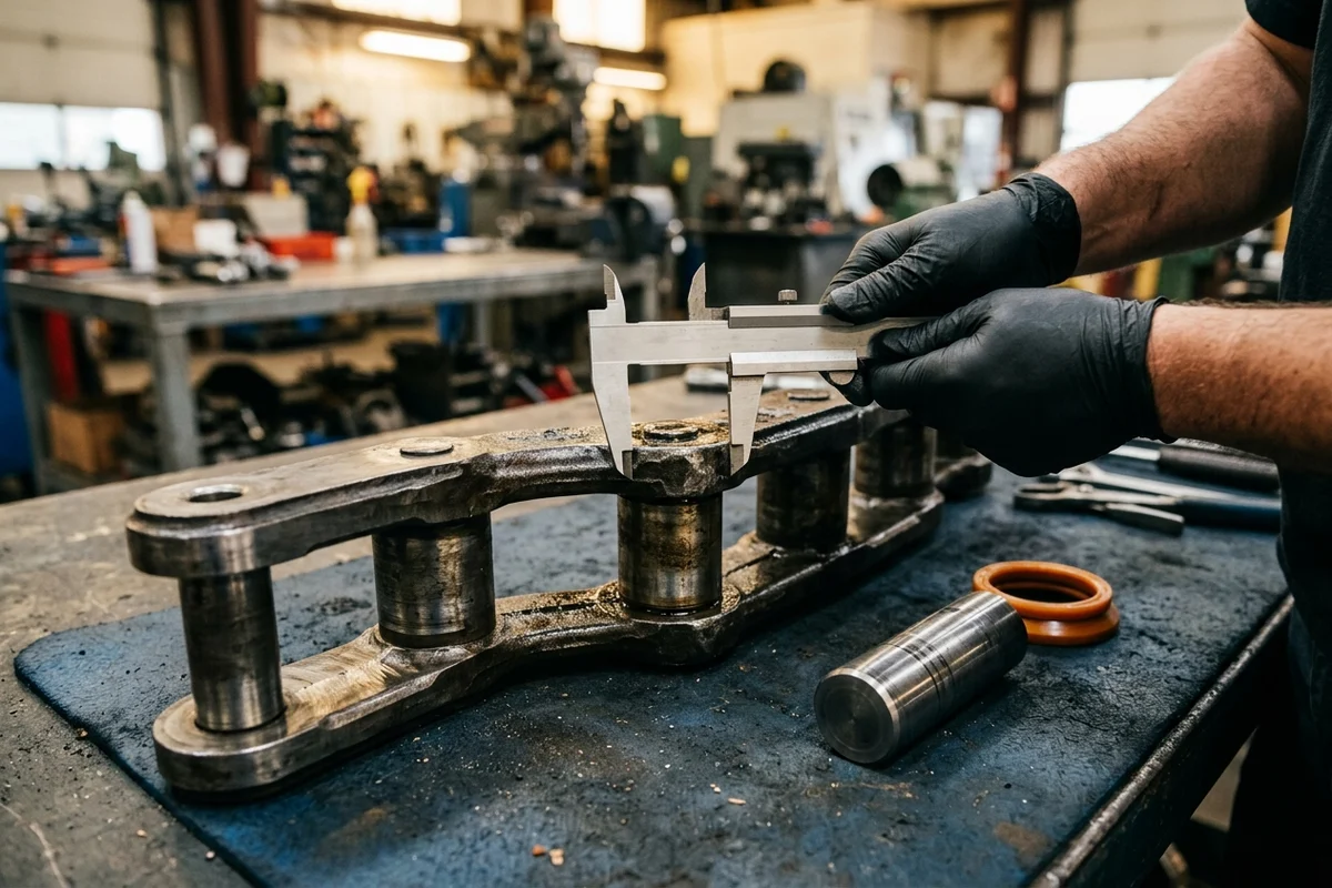
Figure 2: Workbench caliper verification of the carburized steel track bushing outer diameter (D_b), inner rail straddle width (W_rail,in), and induction-hardened link rail height (H_link) alongside the track pin and polyurethane joint seal.
Engineering Rule-of-Thumb (4-Consecutive-Pin Tape Measurement P_nom = L_4-link / 4 vs. Single-Link Stretch Over-Reading Threshold): When identifying the nominal pitch (P_nom) of a worn track chain on the machine → never measure across a single link (1-pitch span) where 2.5 to 4.5 mm of internal pin-and-bushing radial clearance is concentrated; always pull the chain taut in forward travel, measure center-to-center across 4 consecutive link pitches (5 pins, Pin 1 center to Pin 5 center), and divide by 4 (P_meas = L_4-link / 4), because measuring a single stretched link over-reads a worn 190.0 mm chain as 193 to 196 mm (or a worn 171.45 mm chain as 175.0 mm), causing buyers to misorder a 203.2 mm or 175.0 mm track chain that cannot mesh with the drive sprocket tooth pitch circle.
Engineering Rule-of-Thumb (Physical Full-Loop Link Count N_links Chalk-Mark Verification vs. Cab Model Decal Threshold): Before approving any excavator track chain order → chalk-mark the master pin as Link #1 and physically count every individual link section (N_links) around the full track loop rather than relying on the cab model decal (e.g., "CAT 320", "SANY SY215", "Komatsu PC200", or "Kobelco SK200"), because the exact same 20-ton excavator model ships with 45 links on a Standard (STD) undercarriage frame, 46 links on intermediate frames, 49 links on a Long Crawler (LC / NLC) frame, or 51 to 52 links on Super Long Reach (SLR) frames—and a 4-link error (760 mm) renders a 900 kg steel chain impossible to install.
2. OEM Excavator Track Chain Pitch Classes (135 mm to 260 mm) & Cross-Brand Reference Matrix
Standard crawler excavator steel track link assemblies are engineered around eight standardized metric/imperial pitch families (135.0 mm to 260.0+ mm). Use the reference matrix below as an engineering baseline under standard factory configurations, and always verify your specific serial break (ISO 10261 PIN) and physical link count (N_links) before ordering:
Scroll horizontally to view all columns.
Nominal Pitch P_nom (mm / in) & 4-Link New Span (4 * P_nom) | Excavator Tonnage Class & Representative Host Models | Standard Engineering Baselines (4-Link 100% Wear Limit, Bushing OD D_b, Pin OD d_pin, Link Height H_link) | Typical Link Counts (N_links: STD vs. LC / SLR) & Shoe Bolt Grid (D / E x B, Class 12.9 Bolt) | Representative OEM & Berco Cross-Reference Numbers | Dominant Failure Mode & Prevention |
|---|---|---|---|---|---|
135.0 mm (5.31 in)New 4-Link: 540.0 mm | 4–6.5 Ton Mini / Compact Excavator ( SANY SY55C / SY60C, CAT E70B / 305.5E2 / 306, Komatsu PC55MR / PC60-3, Hitachi EX40 / EX45 / ZX55U, Doosan DX55 / S50, Hyundai R55) | • 100% Wear (4-Link): 549.0–551.0 mm (+2.5 mm/link)• Bushing D_b: 40.0 to 41.0 mm• Pin d_pin: 25.4 to 27.0 mm• Link Height H_link: 73 to 76 mm | • Link Counts: 38L (EX40/45), 39L (MX55), 40L (S50 / R55 / SY55C), 42L (CAT E70 / PC60-3)• Shoe Bolts: M12 x 1.25 / 1.5 (12.3 mm link hole) or M14 x 1.5 | • Berco: MT24/42, KM906/42• OEM Refs: 1028077, 961885 (CAT), 201-32-00131 (Komatsu), 9087953 (Hitachi) | Failure mode: Confusing a rubber-track-converted mini excavator idler/sprocket group with a steel-track 135 mm chain group (different idler flange guide width). Prevention: Verify whether the machine currently runs steel links or rubber tracks before ordering. |
154.0 mm (6.06 in)New 4-Link: 616.0 mm | 7–9.5 Ton Midi Crawler Excavator ( SANY SY75C / SY85C, CAT 307E / 308E2, Komatsu PC60-6 / PC75UU / PC78US / PC120-3, Hitachi EX60 / ZX75US, Kobelco SK60 / SK75SR) | • 100% Wear (4-Link): 626.0–628.0 mm (+2.75 mm/link)• Bushing D_b: 46.0 to 47.0 mm• Pin d_pin: 28.6 to 30.0 mm• Link Height H_link: 82 to 85 mm | • Link Counts: 37L (EX60), 38L (SK60), 39L (PC60-6 / PC75 / SY75C), 40L, 43L (PC120-3)• Shoe Bolts: M14 x 1.5 (14.3 mm link hole; 400–450 mm shoes) | • Berco: KM1686/3041, KM965, HT418• OEM Refs: 201-32-00011, 202-32-00010 (Komatsu), 9096710 (Hitachi), 24100N6311F2 (Kobelco) | Failure mode: Ordering a 39L chain (PC60-6 / SY75C) for a 37L (EX60) or 38L (SK60) midi excavator without counting links. Prevention: Chalk-mark and count all links (37L vs. 38L vs. 39L) on the machine. |
171.45 mm / 175.0 mm (6.75 / 6.89 in)New 4-Link: 685.8 / 700.0 mm | 11–16 Ton Small-Medium Excavator ( SANY SY135C / SY155H, CAT E110 / 311 / 312D / 313D / 215, Komatsu PC100-5 / PC120-6 / PC130-8, Hitachi EX100 / EX150 / ZX120 / ZX130, Kobelco SK120 / SK135SR, Volvo EC140B / MX135) | • 100% Wear (4-Link): 697.8 mm (171.45 mm) / 712.0 mm (175.0 mm) (+3.0 mm/link)• Bushing D_b: 50.0 to 54.0 mm• Pin d_pin: 31.75 to 34.0 mm• Link Height H_link: 90 to 95 mm | • Link Counts: 41L (E311 / EX100), 42L (PC100-5), 43L (E110 / SK120 / PC120), 44L (SANY SY135C), 45L (EX150), 46L (MX135 / R130LC), 48L (EX200-1 175.5 mm)• Shoe Bolts: M16 x 1.5 (16.3 mm hole; Pre-torque 175 N*m + 120 deg) | • Berco: CR4854/41, CR1766/43, CR2849/49, KM1262 (175 mm), HT420, HT17 (175.5 mm)• OEM Refs: 4I7479 (CAT), 203-32-00101 (Komatsu), 995398, AT159899, 9066724 (Hitachi), 24100J16939F1 (Kobelco) | Failure mode: Pitch Collision (171.45 mm vs. 175.0 / 175.5 mm)—a worn 171.45 mm chain with +3.5 mm/link internal wear measures 175.0 mm on a single link, tricking buyers into ordering a 175.0 mm chain (KM1262 / HT17) that jams on a 171.45 mm sprocket. Prevention: Measure across 4 link pitches (685.8 mm vs. 700.0 mm) and check stamped link code. |
190.0 mm (7.48 in)New 4-Link: 760.0 mm | 18–24 Ton Standard Crawler Excavator ( SANY SY215C / SY235C, CAT 320B/C/D / 320GC / 323 / 225D, Komatsu PC200-3/5/6/7/8 / PC220, Hitachi EX200-3 / ZX200 / ZX210LC, Kobelco SK200-8 / SK210LC, Doosan DX225LC / S220-3, Hyundai R210-7, Volvo EC210B) | • 100% Wear (4-Link): 772.0–775.0 mm (+3.0 to +3.75 mm/link)• Bushing D_b: 59.0 to 59.3 mm (60.0 mm HD)• Pin d_pin: 38.0 to 38.2 mm• Link Height H_link: 104.0 to 105.0 mm | • Link Counts: 45L (CAT 320 STD, PC200-5/6/7/8 STD, SE210-2), 46L (PC200-3, EX200-3), 49L (SANY SY215C, SK200-8, R210-7, S220-3, CAT 225D, PC200LC), 51L–52L (SLR)• Shoe Bolt Grid: D = 160 mm (outer), E = 125 mm (inner), B = 65 mm (longitudinal); M20 x 1.5 (20.3 mm hole; 430 N*m + 120 deg) or M18 x 1.5 (18.3 mm on PC200-3 KM1170) | • Berco: KM782/45, KM782/49, CR5350/45, CR5011/49, KM1170/46• OEM Refs: 20Y-32-00013, 20Y-32-00014, 206-32-00011 (Komatsu), 9W9354, 6Y8184 (CAT), 9092517 (Hitachi), LQ62D00015F1J1A (Kobelco), 81EM-20010 (Hyundai) | Failure mode: 1) 45L STD vs. 49L LC Link Count Mismatch on PC200 / CAT 320 / SY215C; 2) M18 vs. M20 Shoe Bolt Collision (18.3 mm on KM1170 vs. 20.3 mm on KM782 / CR5350). Prevention: Count all links (45L vs. 46L vs. 49L) and measure bolt hole diameter (18.3 mm vs. 20.3 mm) and 160/125 x 65 mm grid. |
203.2 mm (8.00 in)New 4-Link: 812.8 mm | 25–30 Ton Medium-Large Excavator ( SANY SY265C / SY285, CAT 325B/C/D, Komatsu PC270 / PC300-3 / PC300-5, Hitachi EX300, Kobelco SK260 / SK300, Hyundai R280, Doosan S280) | • 100% Wear (4-Link): 826.8–828.8 mm (+3.5 to +4.0 mm/link)• Bushing D_b: 63.5 to 66.8 mm• Pin d_pin: 41.2 to 42.9 mm• Link Height H_link: 114 to 120 mm | • Link Counts: 45L (CAT 325 STD), 47L (PC300-3/5, EX300, SK300, S280), 48L–50L (LC), 51L (Hyundai R280)• Shoe Bolts: M20 x 1.5 (20.0 mm hole on PC300-3 KM959) or M22 x 1.5 (22.0 mm hole on PC300-5 KM1617; 500 N*m + 120 deg) | • Berco: CR5489/45, KM959/47, KM1617/47, CR5060• OEM Refs: 6Y0854 (CAT), 207-32-00050, 207-32-00101 (Komatsu), 9140549 (Hitachi), 5603941 (Kobelco), 81EM-35010 (Hyundai) | Failure mode: M20 vs. M22 Track Bolt Upgrade Across Generation Breaks—PC300-3 (KM959) drills 20.0 mm shoe bolt holes while PC300-5 (KM1617) drills 22.0 mm bolt holes on the same 203.2 mm (47L) pitch. Prevention: Measure track bolt shank diameter (20 mm vs. 22 mm) before ordering a bare chain. |
215.9 mm / 216.0 mm (8.50 in)New 4-Link: 863.6 / 864.0 mm | 30–40 Ton Heavy Production Excavator ( SANY SY335C / SY365H / SY375H, CAT 330B/C/D / 336D/E / 235, Komatsu PC300-6/7/8 / PC350 / PC400-3/5, Hitachi ZX330 / ZX350 / EX400-1, Hyundai R290-7 / R360LC / R450, Volvo EC360B / SE350) | • 100% Wear (4-Link): 878.0–880.0 mm (+3.6 to +4.0 mm/link)• Bushing D_b: 66.7 to 71.4 mm• Pin d_pin: 44.45 to 47.8 mm• Link Height H_link: 122 to 133 mm | • Link Counts: 45L (CAT 330 / ZX330), 48L (PC300-6 / R290-7 / SE350), 49L (SANY SY365H / CAT 235 / PC400-5 / EX400-1), 51L (R360), 53L (PC400-3 / R450)• Shoe Bolts: M22 x 1.5 (22.3 mm hole on PC400-3 KM973) or M24 x 1.5 / 2.0 (24.3 mm hole on PC400-5 KM1402 / SY365H; 515 N*m + 120 deg) | • Berco: CR5936/45, CR4235, KM2233/48, KM973/53, KM1402/49, MT14A• OEM Refs: 6Y2755, 8E4274 (CAT), 207-32-00300, 208-32-00040, 208-32-00101 (Komatsu), 9202851, 9084353 (Hitachi), 81EH-20010 (Hyundai), 13912646 (SANY SY365H) | Failure mode: Generation Pitch Jump (PC300-5 at 203.2 mm vs. PC300-6/7/8 at 216.0 mm, and PC400-5 at 216.0 mm vs. PC400-6 at 228.6 mm) when buyers order by "PC300" or "PC400" series name without dash generation. Prevention: Lock dash series (-5 vs. -6/-7/-8), machine PIN, and 4-link tape span. |
228.6 mm / 260.0 mm (9.00 / 10.24 in)New 4-Link: 914.4 / 1,040.0 mm | 45–120 Ton Quarry & Mining Excavator ( SANY SY485H / SY500H / SY750H, CAT 345 / 349 / 365 / 374 / 385, Komatsu PC400-6/7/8 / PC450 / PC650 / PC1000 / PC1250, Hitachi ZX470 / EX550 / EX750 / EX1100 / EX1200, Kobelco SK480LC) | • 100% Wear (4-Link): 930.4 mm (228.6 mm) / 1,058.0 mm (260.0 mm) (+4.0 to +4.5 mm/link)• Bushing D_b: 73.0 to 88.9 mm• Pin d_pin: 50.8 to 60.3 mm• Link Height H_link: 140 to 168 mm | • Link Counts: 47L–51L (PC650), 48L–49L (PC400-6, PC1250-7 280 mm, EX1200-6 280 mm), 50L (SK480LC), 52L (EX1100-3), 53L (EX550)• Shoe Bolts: M24 x 1.5 / 2.0, M27 x 2.0, or M30 x 2.0 (Class 12.9) | • Berco: KM2489/49 (228.6 mm), SI1057/50, KM596/51 (260.4 mm), HT229/52 (260.35 mm), KM2346 (280 mm)• OEM Refs: 208-32-00300, 209-32-00101, 21N-32-00101 (Komatsu), 9137494, 9104792, 9276370 (Hitachi) | Failure mode: Extreme quarry rock shock loads causing pin-walking (lateral pin extrusion out of the outer link boss) or catastrophic field downtime if a press-fit chain is shipped without a high-tonnage master pin press or split master link. Prevention: Specify positive pin retention (BPR / PPR ring) and confirm master link tooling (150–200 ton field press vs. Split Master Link). |
3. Joint Sealing (Dry vs. Sealed & Greased vs. Oil SALT) & Master Link Architecture
Not all track chains that share the same 190.0 mm or 215.9 mm pitch are constructed the same internally. Before comparing supplier quotes, verify both the internal pin-to-bushing sealing design and the master joint closure method:
Scroll horizontally to view all columns.
| Architecture Dimension | Sealed & Greased Excavator Track Chain (Polyurethane W-Seal + Synthetic EP Grease) | Dry / Unsealed Excavator Track Chain (Open Metal-on-Metal Pin & Bushing) | Oil-Lubricated Track Chain (SALT — Sealed and Lubricated Track) | Dominant Failure Mode & Prevention |
|---|---|---|---|---|
| Internal Joint Sealing & Lubricant | Counterbored link boss houses a multi-lip polyurethane W-seal (or elastomeric lip seal + thrust ring) packed at assembly with high-viscosity synthetic lithium-complex/molybdenum EP grease (-45 deg C to +50 deg C) | No elastomeric seal in the link counterbore ("None Seal / UNS" suffix, e.g., KM782UNS/49 or KM1170UNS); relies strictly on carburized 20CrMnTi steel-on-steel hardness (HRC 58–62) | Drilled wet track pin with internal oil reservoir plug; joint is evacuated under vacuum and filled with heavy gear oil, sealed by a Belleville spring-loaded polyurethane/nitrile seal assembly | Failure mode: Ordering a low-cost unsealed (UNS / Dry) chain for a high-utilization wet silica sand or quarry excavator, accelerating internal pin/bushing pitch elongation by 20%–35%. Prevention: Specify Sealed & Greased (Polyurethane Seal) as the baseline for 12–50 ton excavators. |
| Internal Pin-to-Bushing Clearance & Noise | Tight assembly clearance filled with damping grease film; eliminates dry metallic squeaking and blocks wet mud/sand ingress (+20% to +30% longer internal wear life than dry chains) | Direct metal-to-metal radial clearance; immune to seal blow-out in hot slag or dry cement clinker, but allows abrasive slurry to enter the pin bore in wet conditions | Slightly greater radial clearance than greased excavator chains to maintain a continuous hydrodynamic oil film during high-speed travel | Failure mode: Polyurethane seals melting or extruding when operating in hot steel-mill slag (> 80–100 deg C ground contact) or packed chemical lime. Prevention: Use Dry (Unsealed / UNS) heavy-case carburized chains in extreme heat or dry cement/slag yards. |
| Primary Machine Application | Standard OEM choice for 8-ton to 80-ton crawler excavators (low travel duty cycle ~10%–15% of engine hours, high digging shock loads, slewing side-thrust) | Light/utility excavators (< 8 tons), low-hour rental/agricultural backup machines, or specialized high-temperature slag/demolition environments | Standard OEM choice for crawler bulldozers (CAT D5–D11, Komatsu D65–D375) and high-mobility mining shovels where travel exceeds 50%–80% of total operating hours | Failure mode: Installing a bulldozer SALT track chain with tall dozer link rails and single-grouser shoes onto a crawler excavator, causing excessive slewing side-load and link cracking. Prevention: Never interchange dozer and excavator track link assemblies even when nominal pitch (190 mm or 203.2 mm) matches. |
Master Joint Closure Method (Press-Fit vs. Easy-Fit vs. Split Alligator) | Usually closed with either a Regular Press-Fit Master Pin (requires 60–100 ton portable hydraulic C-frame track press) or an Easy-Fit / Chamfered Collar Master Pin (slips in with lighter tooling and locks via snap/collar ring) | Closed with a standard Press-Fit Master Pin or T-head / Cotter-Pin Master Pin (on small 135–154 mm chains) | Almost universally closed with a Machined Split ("Alligator") Master Link—two interlocking serrated link halves clamped together by the 4 master track shoe bolts (zero hydraulic track press required) | Failure mode: Driving a regular interference-fit master pin in with a 10 kg sledgehammer and oxy-acetylene torch in the field—mushrooming the pin end, annealing the HRC 58–62 heat treatment, and crushing the polyurethane W-seal. Prevention: Request an Easy-Fit Master Pin or Split Alligator Master Link if your field crew lacks a portable hydraulic track press. |
4. Quantitative Engineering Sizing: 4-Pin Pitch Wear Percentage (Wear_%), Loop Elongation (Delta_L), and Sprocket Pitch-Circle Mismatch
Never guess whether an existing track chain or drive sprocket can be reused, and never accept a single-link caliper reading as nominal pitch. Use the three engineering equations below to calculate exact nominal pitch, percentage internal wear consumed, track adjuster stroke margin, and sprocket-to-chain mismatch cost:
Equation 1: 4-Link Nominal Pitch (P_meas) & Internal Pin/Bushing Wear Percentage (Wear_%)
When you measure center-to-center across 4 consecutive link pitches (Pin 1 to Pin 5) under tension (L_4-link,measured in mm), the average measured pitch per link (P_meas) and the percentage of internal pin-and-bushing wear life consumed (Wear_%) relative to the OEM 0% new span (4 * P_nom) and 100% service wear limit (L_4-link,100%) are governed by:
P_meas [mm]  = L_4-link,measured [mm] / 4
Wear_% [%]   = ( (L_4-link,measured - (4 * P_nom)) / (L_4-link,100% - (4 * P_nom)) ) * 100%
Life_rem [%] = 100% - Wear_%
- 1-Line Worked Example (
20-Ton Excavator 190.0 mm Pitch Chain Internal Wear Audit — CAT 320 / Komatsu PC200 / SANY SY215C): Given a nominal pitchP_nom = 190.0 mm(new 4-link span = 4 * 190.0 = 760.0 mm), an OEM100% internal wear limitofL_4-link,100% = 772.0 mm(+3.0 mminternal radial wear per link), and a field tape measurement across 4 links ofL_4-link,measured = 769.6 mm:P_meas = 769.6 / 4 = 192.40 mm/link --> Wear_% = ((769.6 - 760.0) / (772.0 - 760.0)) * 100% = (9.6 / 12.0) * 100% = 80.0% Worn (20.0% life remaining — schedule chain & sprocket replacement)
Equation 2: Total Unrolled Track Chain Length (L_chain) & Track Adjuster Idler Stroke (Delta_S_idler)
For a track chain with N_links total pitch sections, the total unrolled loop length (L_chain in mm), cumulative loop elongation (Delta_L_loop in mm), and the forward stroke required at the front idler grease tensioner cylinder (Delta_S_idler in mm, which takes up two parallel horizontal track spans—top and bottom) follow:
L_chain [mm]       = N_links * P_meas [mm]
Delta_L_loop [mm]  = N_links * (P_meas - P_nom)
Delta_S_idler [mm] = Delta_L_loop / 2 = ( N_links * (P_meas - P_nom) ) / 2
- 1-Line Worked Example (
Why a 49-Link SANY SY215C / Kobelco SK200-8 Chain Bottoms Out the Idler Adjuster at 100% Wear — and Why Cutting Out 1 Link Fails): On a49-link(N_links = 49)190.0 mmchain (new length L_chain,0% = 49 * 190.0 = 9,310.0 mm), when internal wear reaches+3.0 mm/link(P_meas = 193.0 mm):L_chain,100% = 49 * 193.0 = 9,457.0 mm --> Delta_L_loop = +147.0 mm --> Delta_S_idler = 147.0 / 2 = +73.5 mm forward idler stroke (Cutting 1 link removes 193.0 mm, leaving only +147 - 193 = -46 mm slack, while the 193.0 mm pitch still climbs the 190.0 mm sprocket teeth!)
Equation 3: Drive Sprocket Pitch-Circle Diameter Mismatch (Delta_D_pitch) & Accelerated New-Chain Cost Penalty (Cost_per_hour)
A drive sprocket with Z_s teeth meshing with a chain of pitch P operates on a kinematic pitch-circle diameter D_pitch = P / sin(180 deg / Z_s). When a brand-new chain (P_nom) is installed onto a worn sprocket whose tooth drive faces have hooked to match an old stretched chain (P_worn), the pitch-circle diameter mismatch (Delta_D_pitch in mm) and hourly chain ownership cost (Cost_per_hour = C_chain / L_hours) follow:
D_pitch [mm]         = P [mm] / sin(180 deg / Z_s)
Delta_D_pitch [mm]   = (P_worn - P_nom) / sin(180 deg / Z_s)
Cost_per_hour [$/h]  = C_chain_pair [$] / Service_Life [hours]
- 1-Line Worked Example (
Installing a $3,800 Pair of New 190.0 mm Chains onto Worn 21-Tooth Sprockets vs. Adding $760 for 2 New Sprockets): Given aZ_s = 21-toothsprocket (sin(180/21) = sin(8.5714 deg) = 0.14904) worn toP_worn = 193.0 mmvs. a newP_nom = 190.0 mmchain (pair cost C_chain = $3,800, rated life4,500 hourswith new sprockets vs.1,500 hourson hooked sprockets):Delta_D_pitch = (193.0 - 190.0) / 0.14904 = +20.13 mm pitch-circle mismatch --> Hourly Cost jumps from ($3,800 / 4,500 h = $0.84/h) to ($3,800 / 1,500 h = $2.53/h), destroying $2,533 of track chain life to "save" $760 on two new drive sprockets!
Engineering Rule-of-Thumb (Never Install a New 0% Wear Track Chain Onto a Drive Sprocket With > 30%–40% Hooked Tooth Wear Threshold): Whenever you install a new replacement track link assembly (0% wear, P = P_nom) → always replace the bolted track drive sprockets simultaneously if the existing sprocket teeth exhibit > 30% to 40% profile wear or visible tip hooking/pointing, because a sprocket worn by an elongated old chain (P_worn = 193.0 mm) has a +20.1 mm pitch-circle diameter mismatch against a new 190.0 mm chain, concentrating the excavator's full 180 to 240 kN tractive drawbar pull onto a single sprocket tooth tip, stripping the outer carburized case (HRC 58–62) off the new chain bushings in < 200 to 300 operating hours, and cutting total chain life by 50% to 65%.
5. Track Shoe 4-Bolt Pattern Metrology & ISO 898-1 Property Class 12.9 Torque-Plus-Turn Protocol
Whether you order a Bare Track Link Assembly (to transfer your existing triple-grouser track shoes) or a Pre-Bolted Complete Track Group (chain + shoes factory-torqued), the track shoe bolted joint is the highest-stressed fastener interface on a crawler excavator. Every time the excavator pivots in blasted rock or climbs a stockpile, the grouser tips apply massive prying and bending moments directly against the four track bolts securing each shoe to its left-hand and right-hand forged links.
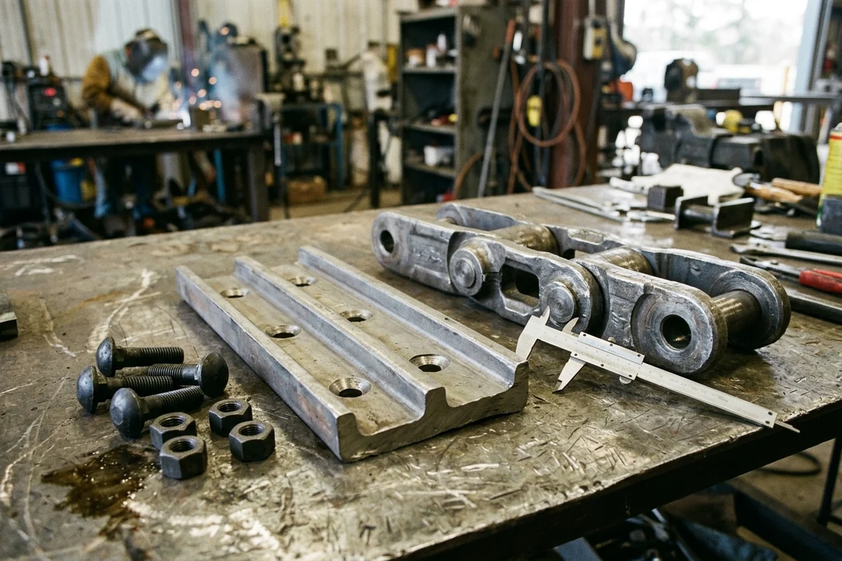
Figure 3: Inspecting the 4-bolt track shoe mounting interface on the workbench—verifying transverse (Dimensions D & E) and longitudinal (Dimension B) bolt-hole center spacing with calipers alongside ISO 898-1 Property Class 12.9 fine-thread plow bolts and induction-hardened square track nuts.
Standard ISO 898-1 Property Class 12.9 Track Shoe Bolt Torque & Torque-Turn (T_pre + 120 deg) Matrix
Standard commercial hardware store bolts (Class 8.8 or Class 10.9 coarse thread) will stretch and shear within hours on an excavator track chain. Undercarriage track bolts are cold-forged from 40Cr / 35CrMo / 42CrMo alloy steel quenched and tempered to ISO 898-1 Property Class 12.9 (nominal tensile strength R_m = 1,220 MPa, yield strength R_p0.2 = 1,100 MPa, core hardness HRC 39–44) with a dome/countersunk collar head, metric fine thread (1.5 mm pitch) to resist vibration self-loosening, and an induction-hardened square track nut that locks rotationally inside the forged link window:
Scroll horizontally to view all columns.
Track Bolt Size & Fine Thread Pitch (ISO 898-1 Class 12.9) | Typical Link Pitch Class & Excavator Applications | Forged Link Bolt Hole Diameter (mm) | Method A: Conventional Final Torque (Lubricated Threads, N*m / ft-lb) | Method B (Preferred): Initial Pre-Torque T_pre + Mandatory Angle Turn (+ 120 deg) | Dominant Failure Mode & Prevention |
|---|---|---|---|---|---|
M14 x 1.5 | 154.0 mm Pitch (7–9.5 Ton: PC60-6 / PC75, SY75C, CAT 308, EX60, SK60) | 14.3 mm | 240 +/- 15 N*m (177 +/- 11 ft-lb) | 110 N*m (81 ft-lb) + 120 deg (1/3 turn) | Failure mode: Over-torquing small M14 bolts with an unregulated 1-inch pneumatic impact gun, snapping bolt shanks during installation. Prevention: Use a calibrated torque wrench (110 N*m) followed by a 120 deg paint-marked angle turn. |
M16 x 1.5 | 171.45 mm / 175.0 mm Pitch (11–16 Ton: SANY SY135C, CAT 312 / E110, PC100-5 / PC120, EX100 / ZX120, SK120) | 16.3 mm | 370 +/- 20 N*m (272 +/- 14 ft-lb; ITR spec: 275–305 ft-lb) | 175 N*m (130 ft-lb) + 120 deg (1/3 turn) | Failure mode: Under-tightened shoes rock against the link face, wearing the raised shoe-support ribs flat and ovalizing the 16.3 mm link holes in < 100 hours. Prevention: Clean mating faces to bare metal and execute the 175 N*m + 120 deg torque-turn sequence. |
M18 x 1.5 | 190.0 mm Pitch (Early 18–20 Ton: Komatsu PC200-3 KM1170, Hitachi EX200-2) | 18.3 mm | 580 +/- 30 N*m (427 +/- 25 ft-lb) | 380 to 405 N*m (280–300 ft-lb) + 120 deg (1/3 turn) | Failure mode: Ordering a modern PC200-6 (20.3 mm hole) chain when reusing old PC200-3 (18.3 mm hole) track shoes, leaving 2.0 mm of radial bolt slop. Prevention: Measure link and shoe bolt hole ID (18.3 mm vs. 20.3 mm) with calipers before ordering. |
M20 x 1.5 | 190.0 mm & 203.2 mm Pitch (18–28 Ton: SANY SY215C / SY235C, CAT 320 / 325, PC200-5/6/7/8, PC300-3, SK200-8, DX225LC, R210-7) | 19.3 to 20.3 mm | 786 +/- 40 N*m (580 +/- 30 ft-lb; ITR spec: 600–660 ft-lb) | 430 N*m (320 ft-lb) + 120 deg (1/3 turn) | Failure mode: Reusing stretched old M20 bolts (180–196 bolts per track) when swapping old shoes onto a new chain, causing cyclic fatigue fracture and lost track shoes. Prevention: Never reuse track bolts; order 4 x N_links new ISO 898-1 Class 12.9 bolts and square nuts per chain. |
M22 x 1.5 | 203.2 mm & 215.9 mm Pitch (28–36 Ton: Komatsu PC300-5/6/7/8, PC400-3, CAT 330, SANY SY335C, Hitachi ZX330) | 22.0 to 22.3 mm | 1,030 +/- 40 N*m (760 +/- 30 ft-lb; ITR spec: 790–875 ft-lb) | 500 N*m (370 ft-lb) + 120 deg (1/3 turn) | Failure mode: Bolting shoes over 200 um of factory yellow/black primer paint on the link rail face; as paint crushes in the first 20 hours, bolt clamp load drops by 60%+. Prevention: Wire-grind paint and rust scale off the link and shoe mating faces before bolting. |
M24 x 1.5 / M24 x 2.0 | 215.9 mm & 228.6 mm Pitch (36–55 Ton: SANY SY365H / SY485H, Komatsu PC400-5/6, CAT 336 / 345, Hitachi EX400 / ZX470) | 24.3 mm | 1,270 +/- 60 N*m (936 +/- 44 ft-lb) | 515 N*m (380 ft-lb) + 120 deg (1/3 turn) | Failure mode: Mixing M24 x 1.5 fine-pitch bolts with M24 x 2.0 coarse-pitch square nuts in the shop bin, stripping threads under 1,270 N*m torque. Prevention: Order factory-matched Class 12.9 bolt-and-nut assemblies bagged together. |
Engineering Rule-of-Thumb (ISO 898-1 Property Class 12.9 Track Shoe Bolt Torque-Plus-Turn T_pre + 120 deg on Bare Paint-Free Mating Faces Threshold): Whenever bolting existing or new triple-grouser track shoes onto a replacement track link assembly → discard all old bolts/nuts, wire-brush or disc-grind both the forged link top bolting pad and the track shoe bottom mating ribs down to bare paint-free steel, lubricate the bolt threads and under-head fillet with light machine oil or anti-seize, seat the square nut flat side against the forged link window, and tighten new ISO 898-1 Property Class 12.9 (HRC 39–44, 1,220 MPa) fine-thread bolts using the 2-stage Torque-Plus-Turn method (e.g., 175 N*m + 120 deg for M16x1.5, 430 N*m + 120 deg for M20x1.5, 500 N*m + 120 deg for M22x1.5, or 515 N*m + 120 deg for M24) in a criss-cross diagonal sequence, because trapped primer paint (150–300 um) or dry-thread friction causes conventional torque wrenches to click out prematurely, allowing the shoe to fret and shear all four bolts within 50 to 150 operating hours.
6. Supply-Scope Envelope Matrix: Bare Track Link Assembly vs. Complete Bolted Track Group
In our undercarriage parts catalog, suppliers and buyers use three distinct ISO 8000-110 units of measure (Piece, Bare Track Chain Assembly, and Complete Bolted Track Group). Always specify which delivery envelope you want quoted—and separate companion rollers, idlers, and sprockets onto their own line items:
Scroll horizontally to view all columns.
| Supply-Scope Dimension | Scope Envelope 1: Individual Forged Track Link / Master Link Kit (UOM: Piece / Repair Kit) | Scope Envelope 2: Bare Track Link Assembly ("Track Chain Only" — UOM: Chain Assembly) | Scope Envelope 3: Complete Bolted Track Group ("Chain + Shoes + Bolts" — UOM: Complete Track Group) | Dominant Failure Mode & Prevention |
|---|---|---|---|---|
| Exact Hardware Included in Box/Pallet | 1x Left-Hand (LH) link, 1x Right-Hand (RH) link, 1x pin, 1x bushing + polyurethane seals (or 1x Split Alligator Master Link pair + 4x master shoe bolts) | Complete factory-pressed continuous loop of N_links (e.g., 45L or 49L) forged LH + RH links, pins, bushings, polyurethane seals, and 1x master pin/joint (NO track shoes or shoe bolts) | Complete N_links sealed-and-greased track link assembly pre-bolted at the factory with N_links rolled boron-steel triple-grouser track shoes (500/600/700/800 mm) using 4 x N_links ISO 898-1 Class 12.9 bolts/nuts torqued to +/- 5% | Failure mode: Requesting a quote for "2x Excavator Tracks" and discovering upon delivery that the supplier shipped Bare Track Chains (Scope 2) without shoes or bolts while your old shoes are bent and worn flat. Prevention: Explicitly state Bare Track Link Assembly (No Shoes) vs. Complete Bolted Track Group (With Shoes & Bolts) on every line. |
| Hardware Excluded (Must Be Ordered on Separate Lines) | Entire remainder of the track chain, track shoes, rollers, idlers, and sprockets | Triple-grouser track shoes (N_links pcs/side), ISO 898-1 Class 12.9 track bolts & square nuts (4 x N_links pcs/side), drive sprockets, bottom/top rollers, and front idlers | Drive sprockets, bottom track rollers, top carrier rollers, front idler & recoil spring adjuster assembly, and final drive / travel motor | Failure mode: Assuming a "Complete Track Group" includes bottom rollers, carrier rollers, idlers, and drive sprockets (which industry catalogs call a "Complete Undercarriage Package"). Prevention: Give sprockets, bottom rollers, top rollers, and idlers their own numbered lines using our multi-brand parts list guide. |
| When This Scope Is Engineeringly Sound | Only when an almost-new chain (< 25% internal pitch wear) suffers an isolated rock fracture on a single link or loses a master pin | When your existing triple-grouser track shoes retain >= 50%–60% of original grouser bar height, have zero plate bending or cracked bolt holes, and you have shop labor + new Class 12.9 bolts to transfer the shoes | When existing grouser bars are worn down near the bolt heads (< 40% height remaining), bolt holes are ovalized, or you need a 2–3 hour crane-and-roll field swap with zero bolt-transfer labor | Failure mode: Paying $1,400–$2,200 in shop labor (16–24 mechanic hours oxy-cutting 360–392 rusted bolts and torquing 360–392 new bolts) to transfer thin, worn-out track shoes onto a brand-new bare chain. Prevention: Compare the incremental price of a factory-bolted Complete Track Group against your workshop's 20-hour bolt-swap labor cost. |
7. 5-Year Excavator Track Chain Fitment, Worn-Sprocket Cascade & Undercarriage TCO Ledger
The undercarriage accounts for up to 50% of a tracked excavator's lifetime maintenance cost. Skipping the 6-dimension checklist or mating a new chain to worn companion components triggers immediate financial losses across five hidden TCO drivers:
Scroll horizontally to view all columns.
| 5-Year Undercarriage TCO Driver | Unverified Model-Decal Ordering / Shortcut Practice | Verified 6-Dimension Metrology + Matched-Wear Protocol | 5-Year Financial & Operational Savings (Per 20–36t Excavator) | Dominant Failure Mode & Prevention |
|---|---|---|---|---|
1. Heavy Pallet Freight Return (45L STD vs. 49L LC Link Count or 171.45 vs. 175 mm Pitch Collision) | Ordering by "CAT 320", "PC200", or "SY135C" cab decal or single-link caliper reading without 4-pin tape span and full-loop link count | Pre-order verification of L_4-link / 4 nominal pitch, chalk-marked N_links count, stamped link forging code, and ISO 10261 PIN (ISO 2859-1 Ac = 0 pre-dispatch check) | Prevents $2,800–$6,500 in round-trip LTL/sea freight on 1,400–2,600 kg steel chain pallets, 15% restocking fees, and 7–21 days of machine-down rental losses ($800–$1,800/day) | Failure mode: A 45-link chain arrives for a 49-link LC excavator frame (or a 175.0 mm chain arrives for a 171.45 mm sprocket) and cannot be installed. Prevention: Submit the completed 6-dimension fitment worksheet before shipment release. |
2. Worn Drive Sprocket Destroying New Track Chain Bushings (Pitch-Circle Mismatch) | Installing a $3,800–$5,600 pair of new 0% wear track chains onto existing drive sprockets with > 30%–40% hooked/pointed tooth wear to "save" $700–$900 | Mandatory tandem replacement of both hardened drive sprockets (HRC 52–56) + Class 10.9/12.9 sprocket bolts whenever installing new track chains | Saves $2,500–$4,200 per replacement cycle by preserving full 4,500–6,000 hour chain bushing life instead of burning through the new chain in 1,500 hours | Failure mode: Hooked sprocket teeth (+20.1 mm pitch-circle mismatch) point-load and strip the carburized 20CrMnTi bushing outer layer in < 200 hours. Prevention: Always order 2x matched drive sprockets on the line directly below your track chains. |
| 3. Reused / Under-Torqued Shoe Bolts & Shoe Transfer Labor Overrun | Reusing old stretched track bolts or spending 20+ hours torch-cutting 392 seized bolts to transfer thin, bent grouser shoes onto a bare chain | Ordering Pre-Bolted Complete Track Groups (when shoes are < 50% life) or installing 100% new ISO 898-1 Class 12.9 bolts via T_pre + 120 deg on clean bare steel | Saves $1,600–$3,400 in workshop mechanic labor and prevents ovalized forged link holes that ruin an entire $2,200 track link assembly | Failure mode: Loose track shoes rock on painted link faces, shearing Class 12.9 bolts and elongating link bolt holes beyond repair in < 100 hours. Prevention: Order pre-bolted track groups or torque new Class 12.9 bolts (T_pre + 120 deg) on bare ground mating faces. |
4. Seized Bottom Roller Cascade & Improper Track Sag (50 mm Target) | Running a $350–$450 bottom track roller with a blown Duo-Cone seal until the roller seizes and drags flat across the new track link rails, or over-tensioning the grease adjuster | 250-hour track sag check (~50 mm / 2 in sag between carrier roller and idler) + 500–1,000 hour 5-system caliper audit + replacing any leaking/seized bottom or carrier roller immediately | Prevents $4,000–$8,000 in premature link rail wear (H_link), idler bushing blowout, and wasted travel hydraulic horsepower | Failure mode: A single seized bottom roller acts like a stationary grinding stone against the moving 35MnB link rails, stripping the 8–12 mm induction-hardened rail layer across all 49 links. Prevention: Inspect bottom/top rollers for oil weeping or flat spots before mounting new chains. |
| 5. Track Adjuster Grease Cylinder Seal Failure & "Cutting a Link" Damage | Torch-cutting 1 link out of a stretched chain when the front idler bottoms out at the end of the track frame | Inspecting the track adjuster grease valve and hydraulic cylinder seal kit and replacing the chain at 100% 4-pin pitch wear (+3.0 to +4.0 mm/link) | Avoids $1,500–$3,500 in cracked front idler yokes, broken recoil springs, and snapped final drive shafts caused by running an over-stretched chain 1 link short | Failure mode: Removing 1 link shortens loop length by 190 mm, but every remaining link still has a 193–194 mm worn pitch that climbs and fractures sprocket teeth under load. Prevention: Never remove a link to tighten a worn-out chain; replace the chain and reseal leaking track adjuster cylinders using our seal kits catalog. |
8. Frequently Asked Questions About Excavator Track Chain Fitment & Replacement
How do I know what size track chain my excavator takes if the part number is rusted off?
Never measure a single worn link and never rely on machine tonnage alone. Instead, follow a four-step physical measurement sequence on the machine:
- Pull the chain taut in forward travel to measure the 4-Link Pitch (
P_nom = L_4-link / 4) from the center of Pin 1 to the center of Pin 5 (4 link sections) with a millimeter steel tape, divide by4, and match the result to the nearest standard nominal pitch (135.0 mm,154.0 mm,171.45 mm,175.0 mm,190.0 mm,203.2 mm,215.9 mm,228.6 mm, or260.0 mm). - Chalk-mark the master pin as
#1and count the Total Links (N_links) around one complete track loop (e.g., 45, 46, 47, 48, 49, or 51 links). - Clamp a vernier caliper across the unworn end of a track bushing to record the Bushing OD (
D_b, e.g.,59.3 mmon a190 mmchain) and measure the Inner Rail Width (W_rail,in) that straddles the roller flanges. - Measure the 4-Bolt Shoe Grid (
D, E, B& Bolt SizeL)—recording the outer transverse bolt spacing (D), inner transverse bolt spacing (E), longitudinal spacing (B), and bolt shank diameter (M16, M18, M20, M22, M24)—and send all six figures with your machine'sISO 10261serial plate photo via our Request a Quote page.
Can I shorten a loose excavator track chain by removing one link instead of buying a new chain?
Cutting out one link ("dropping a link") is a destructive field shortcut that accelerates sprocket and final drive failure. A track chain becomes loose and bottoms out the front idler adjuster because internal pin-and-bushing wear has elongated every single pitch section (for example, from 190.0 mm new to 193.5 mm worn). Removing one link shortens the overall loop circumference by 193.5 mm so the front idler retracts back into the frame, but every one of the remaining 44 or 48 links still has a 193.5 mm elongated pitch. That 3.5 mm/link mismatch (+23.5 mm pitch-circle diameter error on the sprocket) forces the chain bushings to ride high up on the tips of the drive sprocket teeth under extreme tension, rapidly snapping sprocket teeth, cracking bushings, and overloading the final drive planetary hub bearings.
Should I order bare track chains (link assemblies) or complete bolted track groups (with shoes)?
Choose Bare Track Link Assemblies (Scope Envelope 2) only when your existing triple-grouser track shoes retain >= 50% to 60% of their original grouser bar height, have flat unbent plates, and have round, un-wallowed bolt holes—and always budget for 100% new ISO 898-1 Property Class 12.9 track bolts and square nuts (never reuse old bolts). Choose Pre-Bolted Complete Track Groups (Scope Envelope 3) whenever your existing grousers are worn down near the bolt heads, any shoes are bent or cracked, or when workshop labor rates (16 to 24 hours to torch-cut and torque 360 to 400 track bolts) exceed the price difference of factory-torqued track groups.
Are Left (LH) and Right (RH) excavator track chains different?
Each individual forged track link inside a chain is handed—every pitch section consists of one Left-Hand (LH) offset link and one Right-Hand (RH) offset link pressed onto a shared pin and bushing. However, once assembled into a complete Track Link Assembly (Bare Chain) or Complete Track Group, the Left track assembly and Right track assembly on the excavator are identical part numbers (you order Quantity = 2 identical chain assemblies per machine). The only directional requirement occurs during installation on the machine: the narrow (bushing) end of the offset links must lead in the forward travel direction toward the front idler (and the triple-grouser overlap lip must face the correct direction) so the drive sprocket teeth contact the bushing properly during forward travel.
What to Send Us to Verify Your Excavator Track Chain Before Quotation
When you are ready to source replacement track chains, complete track groups, track shoes, Class 12.9 hardware, or companion rollers, idlers, and sprockets via our Request a Quote page, include the five verification items below:
Scroll horizontally to view all columns.
| Verification Evidence to Send | Why It Eliminates Fitment Collisions | Related HeavyPartsSource Guides & Categories |
|---|---|---|
1. Machine Serial Plate (17-Char ISO 10261 PIN) + Stamped Link Forging Code Photo | Locks the exact OEM undercarriage frame variant (STD, LC, NLC, SLR) and cross-references the forged link casting (e.g., CR5350, KM782, KM2233, 20Y-32-00014) | How to Photograph a Part · Find an Excavator Part Number |
2. 4-Link Tape Pitch Measurement (L_4-link in mm) + Full-Loop Chalked Link Count (N_links) | Distinguishes close pitch families (171.45 mm vs. 175.0 mm; 190.0 mm vs. 203.2 mm) and prevents 45L STD vs. 49L LC loop-length errors | Undercarriage Parts Category · Quality Checks |
3. Track Shoe 4-Bolt Grid (D, E, B in mm), Bolt Shank OD (M16–M24), and Shoe Width (mm) | Guarantees your existing triple-grouser shoes will bolt onto a bare chain (or confirms exact shoe width 500/600/700/800 mm for a Complete Track Group) | Part Identification Service · Sourcing and Quotation Process |
4. Bushing OD (D_b), Pin OD (d_pin), Rail Width (W_rail), & Master Joint Preference | Confirms standard vs. Heavy-Duty (EWL) bushing fit against your sprocket roots and selects Press-Fit Master Pin, Easy-Fit Pin, or Split Alligator Master Link | Excavator Final Drive Assembly Scope · Final Drives Category |
5. Itemized Line Scope (Bare Chain vs. Track Group) + Companion Sprockets, Rollers & Idlers | Ensures drive sprockets, bottom track rollers, top carrier rollers, front idlers, and track adjuster seal kits are quoted on clear separate lines | Multi-Brand Parts List Guide · Hydraulic Cylinder Seal Kits |
Copy the Excavator Track Chain 6-Dimension Fitment & Scope Verification Worksheet
Copy the editable worksheet below, fill in the measurements taken from your excavator serial plate and existing track chain, and leave any unmeasured field marked as Unknown — verify before ordering. Paste the completed worksheet into our quote request form along with your machine nameplate and link forging photos, or browse our undercarriage parts, final drives, travel motors, hydraulic cylinders, and seal kits.
Method and Sources
This engineering fitment guide and 6-dimension undercarriage verification checklist were compiled and verified in October 2026 by the HeavyPartsSource undercarriage and drivetrain engineering team using international metallurgy, fastener, and machine-identification standards alongside OEM and tier-1 undercarriage manufacturer technical documentation:
- ISO 683-1 / EN 10083-3 (Heat-Treatable Boron & Cr-Mo Alloy Steels) & Tier-1 Undercarriage Metallurgy Baselines — Forged
35MnB / 40Mn2track links (HRC 32–38core,HRC 52–58induction-hardened rail surface with8–12 mmcase depth),20CrMnTicarburized bushings (HRC 58–62),40Cr / 42CrMo4induction-hardened track pins, and25MnBrolled triple-grouser track shoes (HRC 42–49) (cliktracks-sealed-greased-excavator-chains.txt,feiyueparts-190mm-pc200-cat320-track-link.txt,oem-excavator-track-chain-standards-and-specs.md). - Berco (
MT24,KM906,KM1686,KM965,CR4854,CR1766,KM1262,HT420,CR5350,CR5011,KM782,KM1170,CR5489,KM959,KM1617,CR5936,KM2233,KM1402,KM973,KM2489,KM596), Caterpillar (9W9354,6Y8184,6Y0854,6Y2755), Komatsu (201-32-00131,203-32-00101,20Y-32-00013 / 20Y-32-00014,207-32-00101,207-32-00300,208-32-00300), Hitachi, Kobelco, Hyundai, and SANY (SY135C 44L,SY215C 49L,SY365H 13912646) Cross-Reference Data — Nominal pitch classes (135.0 mmto280.0 mm),STDvs.LClink counts (37Lto53L), bushing/pin diameters (59.3 mm / 38.2 mmon190 mmpitch), and 4-bolt shoe grid dimensions (160 / 125 x 65 mm) (cliktracks-sealed-greased-excavator-chains.txt,bestpartscn-berco-excavator-track-chain-cross-ref.txt,feiyueparts-190mm-pc200-cat320-track-link.txt,astrak-sany-sy215-track-chain-specs.txt). - ISO 898-1 Property Class 12.9 / SAE J429 / JIS B 1180 Fastener Standards & West-Trak / ITR Track Bolt Torque-Turn Specifications — High-tensile
1,220 MPa(HRC 39–44) fine-thread track shoe plow bolts (M14x1.5toM24x1.5/2.0), Method A conventional lubricated torque (370 to 1,270 N*m), and Method B 2-stage Torque-Plus-Turn (T_pre + 120 deg) tightening protocol (oem-excavator-track-chain-standards-and-specs.md,tkv-excavator-steel-tracks-chains.txt). - Heavy Vehicle Inspection (
HVI, How to Inspect Heavy Equipment Undercarriage Wear) & VemaTrack (Recognising Wear on Your Undercarriage Parts) — 4-pin tape pitch elongation measurement, percentage wear formula, tandem sprocket-and-chain replacement rules, seized bottom roller cascade mechanics,50 mm(2 in) track sag targets, and250 / 500–1,000 hourinspection intervals (hvi-track-undercarriage-wear-inspection.txt,vematrack-undercarriage-wear-guide.txt). - TKV Australia (Excavator Steel Tracks & Chains) & MechLink (Track Chain Types: Dry and Lubricated) + ISO 10261:2021 & ISO 8000-110 — Sealed and greased polyurethane-sealed excavator chains versus dry unsealed (
UNS) and vacuum oil-lubricated (SALT) chains with split alligator master links, plusPiecevs.Bare Chainvs.Complete Track Groupprocurement scope separation (tkv-excavator-steel-tracks-chains.txt,mechandlink-dry-and-lubricated-track-chains.txt,hps-undercarriage-category.txt,iso-10261-preview.txt).