
Publisher: HeavyPartsSource
Ordering a replacement hydraulic pump using only a machine model decal (SY215C, EC210B, PC200-8, 320D) or a bare pump casting code (K3V112DT, K3V140DT, K5V200DTH, A10VO85, A11VO130, HPV95, AP2D28, PSVD2-21E) causes input spline mismatches, engine-stalling regulator miscalibrations, blown shaft seals from reversed rotation, and < 30 second dry-start rotating-group seizures. Before releasing a purchase order, lock the complete main pump nameplate, the separate regulator valve-block tag, the physical shaft/flange/port interfaces, and the post-failure system flushing scope on one verification record.
To order a replacement heavy-equipment hydraulic pump without fitment failure or startup destruction, verify seven mandatory engineering parameters for each request line (line-01): (1) the complete main pump nameplate—recording the manufacturer, full model/type code string (Kawasaki K3V112DT-1XER-9N2A, Bosch Rexroth A10VO85DRS/53R-VSC12K04, Danfoss H1P250...), 10-digit material or OEM assembly part number (R902..., 708-2L-00300), and serial number; (2) the separate regulator valve-block nameplate (Kawasaki -9Nxx / -2Nxx / -2Pxx / -9Lxx or Rexroth DR / DRS / LA... / EP2D) plus proportional solenoid voltage (24V DC vs. 12V DC) and connector type (DEUTSCH DT04-2P); (3) the ISO 3019-1 / SAE J744 (SAE A 82.55 mm, SAE B 101.60 mm, SAE C 127.00 mm, SAE D 152.40 mm) or ISO 3019-2 mounting flange pilot diameter and bolt circle; (4) the input shaft spline tooth count z, major outside diameter (mm), and standard (JIS B 1603 / DIN 5480 metric module m = 2.5 vs. SAE J498b / ANSI B92.1 16/32 or 12/24 DP); (5) shaft rotation direction (R = CW vs. L = CCW always viewed facing the input drive shaft) and rear PTO / through-drive auxiliary gear-pump coupling (K01, K68, K04); (6) ISO 6162-1 (Code 61) suction and ISO 6162-2 (Code 62) high-pressure delivery split-flange port dimensions; and (7) the exact supply scope (complete calibrated assembly with regulator and PTO gear pump vs. bare main pump vs. internal rotary group cartridge kit) paired with ISO 4406 <= 18/16/13 case-drain pre-fill and post-failure cooler/tank flushing.
Scroll horizontally to view all columns.
| Verification layer or input parameter | Governing standard or OEM catalog baseline | Why it governs replacement hydraulic pump fitment & survival |
|---|---|---|
1. Main pump nameplate (Model Code + Material P/N + S/N) | Kawasaki KPM (K3V/K5V); Bosch Rexroth RA-A 92703/12.11 (R902...); Danfoss AX152986481244en-001004 (p. 5) | Separates the orderable assembly number from the model code string and serial break; raw housing casting marks never identify internal displacement or porting |
| 2. Regulator valve-block tag & solenoid coil spec | Kawasaki regulator codes (9N, 2N, 2P, 9L, 2C); Rexroth controls (DR, DRS, LA5D–LA9D, ED/ER, EP1D/EP2D); DEUTSCH DT04-2P (IP67/IP69K) | Matches negative flow control (NFC), positive flow control (PFC), or load-sensing (LS) curves to the machine computer and prevents 24V vs. 12V coil burnouts |
| 3. Mounting flange pilot diameter & bolt pattern | ISO 3019-1:2001 (SAE J744): SAE A (82.55 mm), SAE B (101.60 mm), SAE C (127.00 mm), SAE D (152.40 mm); ISO 3019-2 metric (125 / 160 / 180 / 200 mm) | Maintains flange-to-shaft concentricity within <= 0.25 mm and perpendicularity within 0.002/1 (ISO 3019-1 Clause 7) on the engine flywheel housing or splitter box |
| 4. Input drive shaft spline tooth count & pitch profile | SAE J498b / ANSI B92.1 (30 deg 16/32 or 12/24 DP) vs. JIS B 1603 (20 deg) & DIN 5480 (30 deg) metric module (m = 2.5 or 3.0 mm) | Prevents ordering a 14T SAE C spline (31.75 mm OD) when the excavator flywheel coupling requires a 14T metric m = 2.5 spline (35.0 mm pitch dia, ~37.5 mm OD) |
| 5. Shaft rotation direction & rear PTO through-drive | ISO 3019-1, Kawasaki Catalog (p. 5) & Rexroth (p. 3): R = Clockwise (CW) vs. L = Counter-clockwise (CCW) viewed from drive-shaft end; PTO SAE A / B (max 125 N*m) | Reversing CW/CCW rotation starves the suction port and blows out the shaft seal; omitting the rear PTO spline (K01/K68) leaves the pilot/fan gear pump uncoupled |
| 6. Suction, delivery & case-drain port geometry | ISO 6162-1 (SAE Code 61, 3000 psi) suction vs. ISO 6162-2 (SAE Code 62, 6000 psi / 420 bar) delivery split flanges; JIS B 2351 G 3/4 or ISO 11926 UNF drain | Prevents Code 61 vs. Code 62 4-bolt flange spacing collisions (26.2 x 52.4 mm vs. 27.8 x 57.2 mm on 1" ports) and metric (M10/M12) vs. UNC bolt mismatches |
| 7. Supply scope, case-drain pre-fill & system flushing | Rexroth RA-A 92703/12.11 (pp. 5–6, 56): pre-fill housing (0.2–2.5 L) via highest drain port (L/Dr1), case pressure <= 2.0 bar abs, cleanliness ISO 4406 <= 18/16/13 | Prevents receiving an uncalibrated bare pump when a complete assembly was needed, and stops < 30 s dry-start seizure or repeat failure from unflushed brass/steel swarf |
| Dominant failure mode & prevention | Engine lugging/stall from wrong regulator suffix (-2P vs. -9N), spline collision (14T SAE vs. metric), or < 30 s dry-start / repeat swarf seizure | Prevented by 10–25 deg raking-light photos of both pump and regulator tags, caliper OD check on splines/flanges, manual case-drain pre-fill, and cooler/strainer flushing |
Why is a bare hydraulic pump casting code (K3V112DT, A10VO85, HPV95, PSVD2) never enough to approve a replacement?
A base hydraulic pump model cast or stamped onto the main housing—such as Kawasaki K3V63DT, K3V112DT, K3V140DT, K3V180DT, K5V140DTP, or K5V200DTH, Bosch Rexroth A10VO, A11VO, A8VO, or A4VG, Linde HPR / HPV, Komatsu HPV95 / HPV118 / HPV160, Uchida AP2D, or Kayaba (KYB) PSVD2—identifies only the core pump series, nominal geometric displacement V_g (cm^3/rev per rotating group), and housing arrangement (DT = Double Tandem, DP = Double Parallel, S = Single). It does not define how the pump couples to the diesel engine flywheel, how its rear through-drive powers auxiliary pilot or cooling-fan gear pumps, or how its hydro-mechanical and electro-proportional regulators communicate with the excavator's Main Control Valve (MCV) and electronic controller.
As documented in the Danfoss H1P Axial Piston Pump Service Parts Manual (AX152986481244en-001004, page 5), the Kawasaki K3V/K5V Engineering Catalog (kawasaki-k3v-k5v-pump-catalog.txt, pages 5–8), and the Bosch Rexroth A10VO Series 52/53 Technical Data Sheet (RA-A 92703/12.11, pages 2–4), every complete hydraulic pump identity is split across two physical metal tags plus the host machine's 17-character Product Identification Number (ISO 10261:2021 PIN):
- The Main Pump Nameplate: Carries the manufacturer's orderable assembly/material number (e.g., Bosch Rexroth 10-digit
R902..., Danfoss 8-digit Ident No., or OEM assembly P/N), the complete model/type code string (e.g.,K3V112DT-1XER-9N2AorA10VO85DRS/53R-VSC12K04), and the pump serial number (which governs mid-series internal rotating-group and seal-kit breaks). - The Separate Regulator Valve-Block Tag: On excavator main pumps (
Kawasaki K3V / K5V,Rexroth A8VO / A11VO,Komatsu HPV), each horsepower and flow regulator bolted to the side or top of the main pump carries its own riveted aluminum tag (such asKR3G-9N04-1,-2Nxx,-2Pxx, or-9Lxx). If a previous mechanic swapped regulators during an earlier repair, or if the main tag only lists the bare pump body, the regulator tag is the sole record of the pilot control curve (Pi), companion-pump horsepower summing (P2), and proportional reducing valve (PRV) solenoid calibration.
OEM Heavy-Equipment Hydraulic Pump & Regulator Tag Decoding Matrix
Before comparing replacement pump assemblies or internal repair kits in our hydraulic pumps category, clean and transcribe all lines from both the main pump dataplate and the regulator tag across the four core equipment pump architectures:
Scroll horizontally to view all columns.
| Hydraulic pump architecture & major OEM families | Complete model code & sub-tag syntax | Critical internal & control variables encoded in the suffix | Where the physical tags & backup stampings are located | Dominant failure mode & prevention |
|---|---|---|---|---|
1. Tandem Axial-Piston Excavator Main Pumps (Kawasaki K3V63DT / K3V112DT / K3V140DT / K3V180DT / K3V280DTH, K5V80DT / K5V140DTP / K5V200DTH, Rexroth A8VO, Komatsu HPV95/118/160, Uchida AP2D, Kayaba PSVD2) | Kawasaki: [Series: K3V/K5V][Displ: 63–280][Type: DT/DP/S][Aux: H/P]-[4-Char Design Code: 1XER / 100R / HN0V]-[Regulator Code: 9N / 2N / 2P / 9L / 2C][Design Suffix: 01 / 2A] (Kawasaki Catalog pp. 5–8)Komatsu: 708-2L-00300 (10th digit = revision) | Attachment: H = centrifugal charge pump; P = rear PTO gear drive.Design Code ( 1XER, 1X9R): locks input spline (14T vs. 17T metric/SAE) and port orientation.Regulator ( 9N vs. 2P vs. 9L): 9N = Negative Flow Control (NFC) + Total HP + Electric Variable HP; 2P = Positive Flow Control (PFC) + Total HP; 9L = Load Sensing (LS) + Total HP | Main Pump Tag: riveted to the front or side cast-iron pump housing near the input flange. Regulator Tags (x2): riveted separately onto the front ( P1) and rear (P2) aluminum regulator valve blocks bolted to the main housing | Failure mode: Ordering a bare "K3V112DT" for a 21-ton excavator (SY215C, EC210B, DX225, SK200-8) without the -1XER-9Nxx suffix, resulting in a mismatched input spline or a Positive Flow (2P) regulator installed on a Negative Flow (9N) MCV—causing immediate engine stalling or zero boom speed. Prevention: Photograph both the main pump tag and the 4-character regulator tag before ordering. |
2. Open- & Closed-Loop Single / Swing / Fan Axial-Piston Pumps (Bosch Rexroth A10VO / A10VSO Series 31/52/53, A11VO, A4VG, Linde HPR / HPV, Danfoss H1P) | Rexroth: 10-digit Material No. (R902...) + Type Code A10VO85DRS/53R-VSC12K04 (RA-A 92703/12.11 pp. 2–4)Danfoss: 8-digit Ident No. (83038133) + 29-char Model Code (H1P250 R A A...) (AX152986481244en-001004 p. 5) | Rexroth Control: DR = pressure cut-off; DFR/DRS = pressure + flow (X-T open vs. plugged); LA5D–LA9D = power control (10–230 bar start setting); ED71/ER71 (12V) vs. ED72/ER72 (24V); EP1D/EP2D (12V/24V proportional).Through-Drive: N00 (none) vs. K01 (SAE A 9T), K68 (SAE B 13T), K04 (SAE BB 15T), K15 (SAE C 14T) | Riveted aluminum or laser-etched stainless nameplate on the side of the main housing; combination tandem pumps join two full type codes with a "+" sign (A10VO85...K04 + A10VO45...N00 per Rexroth p. 54) | Failure mode: Ordering an A10VO or A11VO by displacement (45, 85, 130 cc) alone and receiving an N00 blind rear cover instead of a K68 (SAE B 13T) through-drive, or a DFR (X-T open bleed orifice) instead of a DFR1 / DRS (X-T plugged). Prevention: Always provide the 10-digit R902... material number and the complete hyphenated type code string. |
3. Tandem / Triple External Gear Pumps & Pilot Charge Pumps (Shimadzu SGP1/SGP2, Permco, Parker/Commercial, Casappa KP/PLP, Rexroth AZPF, integrated K3V/K5V PTO pilot pumps) | Manufacturer Series + Section Displacement String (cm3/rev per gear section, e.g., AZPF-12-016+011-RRR...) + Flange Code + Shaft Code + Port Type | Front mounting pilot (SAE A 82.55 mm vs. SAE B 101.60 mm), input spline (9T, 11T, 13T), rotation (R = CW vs. L = CCW), and individual gear housing widths W_gear,1 / W_gear,2 / W_gear,3 | Stamped onto the cast-iron front mounting flange or rear cover, or printed on an anodized aluminum plate riveted to the gear body | Failure mode: Replacing a rear pilot charge gear pump by bolting pattern alone while delivering 22 cc/rev instead of 14 cc/rev, overheating the pilot circuit and blowing the pilot relief valve, or installing a CW gear pump on a CCW rear PTO pad. Prevention: Record the stamped code on the gear pump flange and measure each cast gear-section width with a caliper. |
4. Hydro-Mechanical Regulators & Proportional Solenoid Blocks (Kawasaki KR3G / K5V Regulators, Rexroth DRE / EP / ED / ER, Komatsu PC-EPC / LS-EPC, KDRDE5K proportional valves) | Regulator Tag Code (-9N01, -2N05, LA7D) + Solenoid Part No. (e.g., KDRDE5K-31/30C50-140, R902601804) + System Voltage (24V DC vs. 12V DC) | Spring preload range (10–35 bar on LA5D vs. 141–230 bar on LA9D), pilot port thread (G 1/4 vs. UNF), maximum current limit (I_max = 600 mA at 24V vs. 1200 mA at 12V per Rexroth p. 2), and DEUTSCH DT04-2P connector keyway | Regulator code stamped on a small metal plate riveted to the regulator body; solenoid P/N, pressure range, and voltage (24V DC) laser-etched on the cylindrical coil sleeve | Failure mode: Bolting a 12V DC (I_max = 1200 mA) proportional solenoid onto a 24V DC excavator harness—or exceeding I > 600 mA at 24V on an ER solenoid (Rexroth p. 2 Note 5)—causing immediate coil burnout or dangerous hydraulic pressure overload. Prevention: Photograph the regulator plate and solenoid coil sleeve (see our solenoid and main control valves category). |
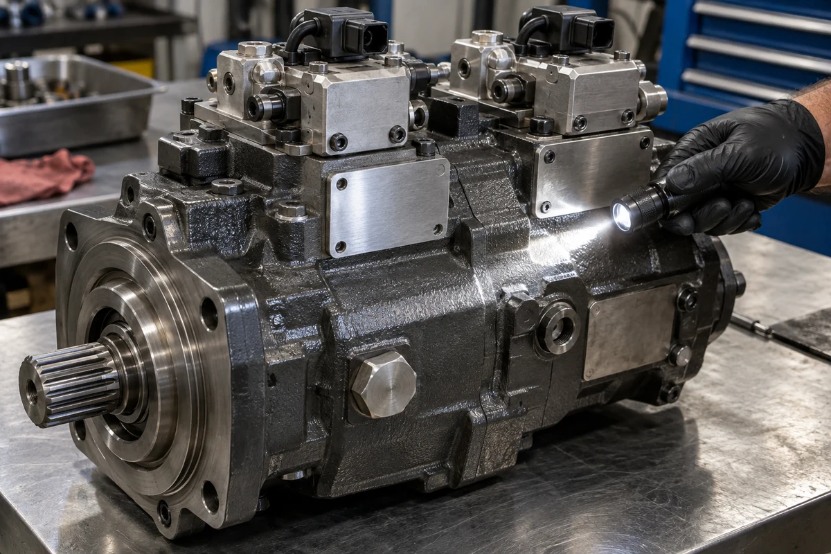
Dual-nameplate inspection on a tandem excavator main pump: use a 10–25° oblique raking LED light with camera flash OFF to capture both the main pump housing tag (model code, OEM part number, and serial break) and the separate aluminum regulator tag bolted to the control valve block.
Engineering Rule-of-Thumb (Bare Pump Casting K3V112DT / A10VO vs. 4-Character Design & Regulator Tag Suffix + Solenoid Voltage Threshold): If a replacement hydraulic pump request specifies only a base housing casting or series designation (Kawasaki K3V63DT / K3V112DT / K3V140DT / K5V200DTH, Bosch Rexroth A10VO / A11VO / A8VO, Uchida AP2D, or Kayaba PSVD2) without the 4-character design code (-1XER, -1X9R, -100R, -HN0V), the separate regulator tag suffix (-9Nxx, -2Nxx, -2Pxx, -9Lxx, or DRS / LA... / EP2D), and the proportional solenoid voltage (24V DC vs. 12V DC) → halt order release and photograph both the main pump nameplate and the regulator valve-block tag under 10–25 deg raking light, because identical bare pump castings are machined with incompatible input splines, negative versus positive flow control curves (Pi), and 12V/24V proportional coils (I_max = 1200 mA at 12V vs. 600 mA at 24V per Rexroth RA-A 92703/12.11 p. 2) that cause immediate engine stalling or coil burnout if mismatched.
Takeaway: Never approve a hydraulic pump replacement from a raw foundry casting mark or machine boom decal alone—always pair the host machine's 17-character ISO 10261:2021 PIN (see our excavator part number lookup guide) with macro photos of both the main pump plate and the regulator tag taken using our 5-shot part photography checklist.
How do you verify mounting flanges, input shaft splines, rotation direction, rear PTO drives, and flange ports before ordering?
When a hydraulic pump's external nameplate has been sheared off by rock debris, sandblasted during a repaint, or swapped with an unlabeled aftermarket housing, physical metrology across five mechanical interfaces is required before a replacement unit can be matched. Even when the tag is readable, cross-checking these five physical interfaces prevents costly surprises caused by mid-series OEM drivetrain revisions or unrecorded field modifications.
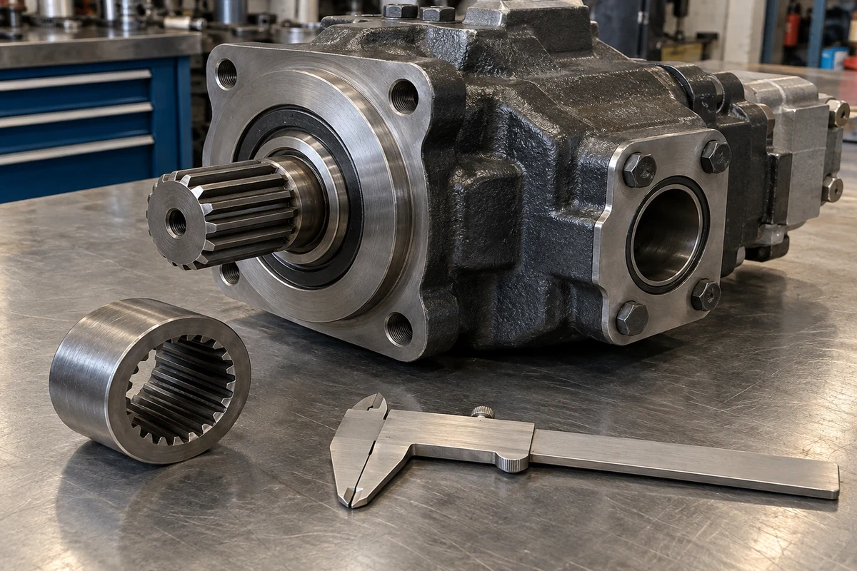
Pre-order mechanical interface metrology: counting spline teeth is never
sufficient—measure the spline outside diameter with a vernier caliper to
separate metric module shafts (JIS B 1603 / DIN 5480) from inch (SAE J744) splines, and verify the circular mounting pilot and 4-bolt split
flange ports.
1. Input Shaft Spline Metrology: Why a 14T or 17T Metric Module (JIS B 1603 / DIN 5480) Shaft Will Not Fit an SAE J744 Coupling
The most common mechanical fitment error in excavator hydraulic pump replacement is assuming that "14 teeth (14T)" or "17 teeth (17T)" uniquely defines an input spline shaft. In heavy-equipment hydraulics, two incompatible involute spline systems exist side by side:
- North American Inch Diametral-Pitch (
DP) Splines (SAE J744 / SAE J498b / ANSI B92.1,ISO 3019-1): Use a uniform30 degpressure angle and fractional Diametral Pitch (16/32 DP,12/24 DP,8/16 DP), where the first number (DP_pitch) governs the pitch circle diameter and the second number (DP_stub) governs tooth stub height. - Metric Module (
m) Involute Splines (JIS B 1603at20 degpressure angle on Japanese/Asian excavator pumps, andDIN 5480 / ISO 4156at30 degpressure angle on European pumps): Sized by metric modulem(mmof pitch diameter per tooth, typicallym = 2.0, 2.5, or 3.0 mm).
For a spline with tooth count z, metric module m (mm), or inch diametral pitch DP (teeth/inch), the reference pitch circle diameter d (mm) and nominal flat-root major outside diameter d_a1 (mm) obey the conversion equations:
Metric Spline (JIS B 1603 / DIN 5480): d_metric = m * z [mm], d_a1_metric approx m * (z + 1.0) [mm]
Inch Spline (SAE J744 / ANSI B92.1): d_SAE = (z / DP) * 25.4 [mm], d_a1_SAE = ((z + 1) / DP) * 25.4 [mm]
As shown in the Kawasaki K3V / K5V Catalog (kawasaki-k3v-k5v-pump-catalog.txt, page 10, Dimensions of shaft end), Kawasaki uses both standards within the exact same K3V product family:
-
K3V63DT(14TSAE12/24 DP,30 degpressure angle): Pitch diameterd_SAE = (14 / 12) * 25.4 = 29.63 mm(29.6 mmin catalog), major outside diameterd_a1 = (15 / 12) * 25.4 = 31.75 mm(1-1/4 inStandardSAE C). -
K3V112DT(14TJIS B 1603Metric Modulem = 2.5 mm,20 degpressure angle): Pitch diameterd_metric = 2.5 * 14 = 35.00 mm, major outside diameterd_a1 approx 2.5 * 15 = 37.50 mm. -
K3V140DT,K5V140DTP, andK5V200DTH(17TJIS B 1603Metric Modulem = 2.5 mm,20 degpressure angle): Pitch diameterd_metric = 2.5 * 17 = 42.50 mm, major outside diameterd_a1 approx 45.00 mm—whereas a17TSAE CC(12/24 DP,30 deg) shaft on a Bosch RexrothA10VO100(RA-A 92703/12.11p. 52) has a pitch diameter of(17 / 12) * 25.4 = 35.98 mmand a major outside diameter of38.10 mm(1-1/2 in)! -
Worked Example (
14TSpline Collision BetweenSAE C 12/24 DPandJIS B 1603 m = 2.5): Suppose a buyer orders a replacement pump by stating only "14-tooth spline shaft" without measuring the shaft OD with a vernier caliper. Comparing the two14Tshafts (z = 14):Delta d_a1 = d_a1_metric(14T, m=2.5) - d_a1_SAE(14T, 12/24 DP) = 37.50 mm - 31.75 mm = +5.75 mm (+0.226 in diameter mismatch)A
14TmetricK3V112DTshaft (37.50 mmOD) is5.75 mmtoo large to enter a31.75 mm(1-1/4 inSAE C) flywheel coupling hub, while a31.75 mmSAE C shaft inserted into a37.50 mmmetric hub has zero tooth engagement and spins freely.
2. Mechanical Interface Verification Matrix (ISO 3019-1 / SAE J744, ISO 3019-2, Rotation, Through-Drive & ISO 6162 Ports)
Verify all five mechanical interfaces against the standard baselines below before confirming an order:
Scroll horizontally to view all columns.
| Mechanical interface dimension | Standard engineering baseline (ISO / SAE / JIS / OEM) | Exact dimensions & codes to measure or transcribe | How to verify on the bench (+/-0.1 mm caliper or visual rule) | Dominant failure mode & prevention |
|---|---|---|---|---|
| 1. Front Mounting Flange Pilot & Bolt Circle | ISO 3019-1:2001 (SAE J744 inch series):• SAE A (82-2): 82.55 mm (3.250") pilot, 106.4 mm 2-bolt• SAE B (101-2 / 101-4): 101.60 mm (4.000") pilot, 146.0 mm 2-bolt or 127.0 mm BC (89.8 mm sq) 4-bolt• SAE C (127-2 / 127-4): 127.00 mm (5.000") pilot, 181.0 mm 2-bolt or 161.9 mm BC (114.5 mm sq) 4-bolt• SAE D (152-4): 152.40 mm (6.000") pilot, 228.6 mm BC (161.6 mm sq) 4-boltISO 3019-2 / Kawasaki K3V/K5V Metric 4-Bolt (Catalog p. 10):• K3V63 / K5V80: D2 = 125 mm pilot, D1 = 180 mm BC (4x18 mm holes)• K3V112 / K5V140: D2 = 160 mm pilot, D1 = 224 mm BC (4x22 mm holes)• K3V140 / K5V200: D2 = 180 mm pilot, D1 = 250 mm BC (4x22 mm holes)• K3V280: D2 = 200 mm pilot, D1 = 300 mm BC (4x26 mm holes) | Raised circular spigot (pilot) outside diameter D2 (mm), pilot register depth (mm), bolt hole count (2-bolt vs. 4-bolt), bolt circle diameter D1 (or center-to-center square spacing), and hole diameter d | Measure the raised circular pilot spigot OD D2 across the center with vernier calipers (e.g., 101.60 mm = SAE B, 127.00 mm = SAE C, 160.0 mm = K3V112 / K5V140 metric) and measure bolt-hole center spacing | Failure mode: Radial shaft side-loading (> 0.25 mm runout violation under ISO 3019-1 Clause 7) or inability to bolt the pump to the engine flywheel bellhousing because an SAE C (127.0 mm) flange was supplied instead of a 160.0 mm metric pilot. Prevention: Record pilot OD D2, bolt count, and diagonal bolt-circle diameter D1 in mm. |
2. Input Drive Shaft (Spline / Keyed / Tapered) | SAE J744 / ANSI B92.1 (30 deg Involute Splines):• SAE A: 9T 16/32 DP, 15.88 mm (5/8") OD• SAE B: 13T 16/32 DP, 22.22 mm (7/8") OD• SAE BB: 15T 16/32 DP, 25.40 mm (1") OD• SAE C: 14T 12/24 DP, 31.75 mm (1-1/4") OD (K3V63DT)• SAE CC: 17T 12/24 DP, 38.10 mm (1-1/2") OD• SAE D/E: 13T 8/16 DP, 44.45 mm (1-3/4") ODJIS B 1603 (20 deg) & DIN 5480 (30 deg) Metric Module Splines (Kawasaki Catalog p. 10):• K5V80: 12T, m = 2.5, d = 30.0 mm (~32.5 mm OD)• K3V112: 14T, m = 2.5, d = 35.0 mm (~37.5 mm OD)• K3V140 / K5V140 / K5V200: 17T, m = 2.5, d = 42.5 mm (~45.0 mm OD)• K3V280: 18T, m = 3.0, d = 54.0 mm (~57.0 mm OD) | Shaft type (-4 spline vs. -1/-2 parallel keyed vs. -3 conical tapered per ISO 3019-1 Clause 5.2), exact tooth count z, major tip diameter d_a1 (mm), and exposed shaft length from mounting flange face (L2 = 70 to 150 mm on K3V/K5V) | Count spline teeth z (mark Tooth #1 with a paint pen), measure outer tip diameter d_a1 (mm) and root diameter with vernier calipers, and measure shaft stick-out length L2 from the flange mounting surface | Failure mode: Stripping the plastic/steel flywheel coupling hub or failing to slide into the hub because a 14T or 17T spline was ordered by tooth count alone without checking 31.75 vs. 37.50 mm (14T) or 38.10 vs. 45.00 mm (17T) OD. Prevention: Never accept a spline specification without both tooth count z and caliper-measured major OD d_a1 (mm). |
3. Direction of Shaft Rotation (CW / R vs. CCW / L) | ISO 3019-1, Kawasaki Catalog (pp. 5, 9) & Rexroth RA-A 92703/12.11 (p. 3):• R (Clockwise / Right-Hand / CW): shaft rotates clockwise when viewed directly looking at the front drive shaft end• L (Counter-Clockwise / Left-Hand / CCW): shaft rotates counter-clockwise when viewed looking at the drive shaft end | Nameplate rotation letter (R or L), cast arrow on the pump housing, and prime-mover drive arrangement (direct engine flywheel mount vs. reversing splitter gearbox) | Stand facing the front input spline shaft (looking toward the rear of the pump) and trace the direction of rotation; on external gear pumps with no arrow, the larger port is always the suction inlet (fluid travels around the outer gear housing from suction to pressure) | Failure mode: Viewing rotation from the rear of the pump or assuming all pumps are CW (R), resulting in a reversed valve plate and internal charge pump—causing immediate cavitation, zero output pressure, and a blown front shaft lip seal within seconds. Prevention: State CW (R) or CCW (L) explicitly viewed from the input drive shaft end. |
| 4. Rear PTO / Through-Drive Auxiliary Pad | Kawasaki K3V/K5V (P suffix, Catalog pp. 9–10) & Rexroth A10VO (RA-A 92703/12.11 pp. 4, 53):• N00 (or blank): No through-drive (blind rear cover)• K01 (SAE A 82-2): 82.55 mm pilot, 2-M10 (106 mm spacing), 9T 16/32 DP (K3V63/112, K5V80/140 standard PTO, max 125 N*m)• K52: SAE A 82-2, 11T 16/32 DP• K68 (SAE B 101-2): 101.60 mm pilot, 2-bolt, 13T 16/32 DP• K04: SAE B 101-2, 15T 16/32 DP• K15 / K07 (SAE C 127-4 / 127-2): 127.00 mm pilot (4-M12 on K3V140 / K5V200), 14T 12/24 DP | Presence of rear auxiliary PTO pad (Yes / No), rear pilot bore ID (82.55 mm SAE A vs. 101.60 mm SAE B), internal coupling spline tooth count (9T, 11T, 13T, 14T, 15T), and whether the attached pilot/fan gear pump is included in the quote | Inspect the rear cover of the pump: if an auxiliary pilot or cooling-fan gear pump is bolted to the back, measure the recessed female pilot bore (82.55 vs. 101.60 mm), count the internal female coupling teeth, and check the O-ring seal groove | Failure mode: Ordering a standard DT or N00 pump when the machine uses a DTP or K01/K68 through-drive, leaving the mechanic with no rear spline coupling or mounting pad to attach the pilot charge pump or hydraulic fan pump. Prevention: Photograph the rear end cap and specify both the through-drive code and whether the rear gear pump is included. |
| 5. Suction, Delivery & Case-Drain Flange Ports | ISO 6162-1 (SAE Code 61, 3000 psi) Suction Ports (Kawasaki p. 10):• 2-1/2" (60 mm bore): 50.8 x 88.9 mm (M12x18) on K3V63/112, K5V80/140• 3" (76 mm bore): 61.9 x 106.4 mm (M16x24) on K3V140 / K5V200ISO 6162-2 (SAE Code 62, 6000 psi / 420 bar) Delivery Ports:• 3/4" (DN 19): 23.8 x 50.8 mm (M10x16) on K3V63/112, K5V80/140 (vs. Code 61 22.2 x 47.6 mm)• 1" (DN 25): 27.8 x 57.2 mm (M12x22) on K3V140 / K5V200 (vs. Code 61 26.2 x 52.4 mm)• 1-1/4" (DN 32): 31.8 x 66.7 mm (M12x20) on K3V280 (vs. Code 61 30.2 x 58.7 mm)Case Drain ( Dr1 / Dr2 or L / L1): JIS B 2351 G 1/2 or G 3/4 vs. ISO 11926 UNF (3/4-16 / 7/8-14 / 1-1/16-12 UN) | Port position (rear axial vs. side radial vs. opposite-side through-drive), split-flange rectangular bolt-hole center spacing (a x b in mm within +/-1.0 mm per ISO 6162), port bore c (mm), fixing thread (Metric M10/M12/M16 vs. UNC 3/8"-16 / 7/16"-14), and case-drain thread form (BSPP/G vs. UNF O-ring boss) | Measure the rectangular 4-bolt hole center-to-center spacing (a x b in mm) across every suction and high-pressure delivery port face with calipers, check for an 'M' stamp (metric threads per ISO 6162), and thread-gauge the case-drain and pilot ports | Failure mode: Trying to bolt an excavator's 1" ISO 6162-2 Code 62 (27.8 x 57.2 mm) high-pressure delivery steel pipe onto a pump machined with ISO 6162-1 Code 61 (26.2 x 52.4 mm) ports, or stripping UNC inch port threads (Rexroth code 61/62) with M10/M12 metric bolts. Prevention: Measure the 4-bolt flange rectangle (a x b in mm) and confirm Metric vs. UNC/UNF port threads before ordering. |
Engineering Rule-of-Thumb (Shaft Rotation Viewing Convention CW/R vs. CCW/L & 14T / 17T Metric Module vs. SAE Spline Caliper Threshold): If a replacement hydraulic pump is being identified from physical inspection or cross-referenced across 12T / 13T / 14T / 15T / 17T / 18T splined shafts → always establish shaft rotation direction (R = Clockwise vs. L = Counter-Clockwise) while looking directly into the front input drive-shaft end toward the pump housing (ISO 3019-1, Kawasaki Catalog p. 5, Rexroth RA-A 92703/12.11 p. 3) and measure both the spline tooth count z and the outside major diameter d_a1 (mm) with a vernier caliper, because a 14T JIS B 1603 metric module m = 2.5 shaft (K3V112DT, OD ~37.5 mm) is +5.75 mm larger than a 14T SAE C 12/24 DP shaft (K3V63DT, OD 31.75 mm), a 17T metric m = 2.5 shaft (K3V140DT / K5V200DTH, OD ~45.0 mm) is +6.90 mm larger than a 17T SAE CC 12/24 DP shaft (OD 38.10 mm), and reversing CW/CCW rotation starves the suction port and blows out the shaft seal on startup.
Takeaway: Never write "14-spline shaft" or "standard flange" on a purchase order—record the exact tooth count z, caliper-measured shaft outside diameter d_a1 (mm), pilot register diameter D2 (mm), rotation (CW/R vs. CCW/L from shaft end), and ISO 6162 Code 61/62 port bolt spacing (a x b in mm).
How do you compare replacement supply scopes: complete assembly, bare pump, internal rotary group cartridge, or regulator rebuild?
A low quotation price on a replacement hydraulic pump is meaningless until you verify the physical assembly boundary. In heavy-equipment parts sourcing, suppliers use the phrase "replacement hydraulic pump" to describe four completely different bills of materials—ranging from a bench-calibrated complete assembly down to a bare cast-iron housing stripped of its $1,200+ regulators and rear pilot gear pump:
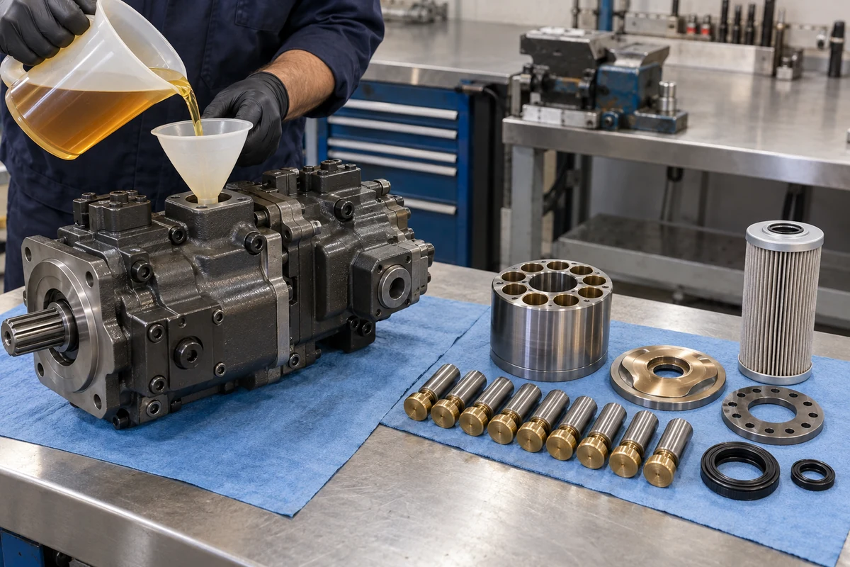
Comparing hydraulic pump replacement scopes and pre-startup preparation: a complete tandem pump assembly with calibrated regulators (left, shown being pre-filled with clean hydraulic oil via the upper case-drain port) versus an internal axial-piston rotary group kit (cylinder block, 9 bronze-shoe pistons, retainer plate, spherical valve plate, and seal kit, right).
Scroll horizontally to view all columns.
| Supply scope tier | Standard bill of materials (BOM) included | What is OMITTED (must be transferred from old pump or ordered separately) | When to select this supply scope | Dominant failure mode & prevention |
|---|---|---|---|---|
1. Complete Calibrated Pump Assembly (Assy with Regulators & PTO Gear Pump) | Front & rear main pump housings + new rotating groups + drive shafts & bearings + both hydro-mechanical/proportional regulators (-9Nxx / DRS) + proportional solenoid valves (24V/12V) + attached rear PTO pilot/charge gear pump; bench-tested to target pressure/flow curve | External ISO 6162 split-flange clamps/bolts, suction manifold elbow, flexible case-drain hose, and tank return/suction filters | Catastrophic internal pump failure (brass/steel swarf throughout housing), cracked pump casing, worn regulator bores, or urgent field turnaround where zero bench re-calibration time is available | Failure mode: Assuming "Complete Pump" automatically includes the rear piggyback cooling-fan gear pump when the machine uses a custom 3-stage rear pump. Prevention: Confirm in writing: Complete main pump assembly INCLUDING front/rear regulators, 24V solenoids, AND rear PTO pilot gear pump. |
2. Bare Main Pump Assembly (Without Regulators or Rear PTO Pump) | Main pump housing + internal axial-piston rotating groups, shafts, swashplates, bearings, and shaft seals (bare power section only) | Top/side horsepower & flow regulators (P1/P2), proportional solenoid coils, and rear PTO auxiliary gear pump (buyer must unbolt and transfer these from the failed pump) | Only when the original regulators and rear PTO gear pump are verified undamaged, free of metallic swarf, and the workshop has hydraulic test-bench or machine-monitor pressure/flow calibration capability | Failure mode: Bolting contaminated old regulators (packed with brass slipper swarf from the failed pump) onto a brand-new bare pump—sticking the regulator spool and destroying the new rotating group within minutes. Prevention: Never transfer old regulators after a catastrophic failure without ultrasonic teardown cleaning, or order Scope 1 (Complete Assembly). |
3. Internal Rotary Group Cartridge Kit (Rebuild Kit) | Matched cylinder block (barrel), 9 (or 7/11) piston-and-bronze-slipper-shoe assemblies, spherical or flat bimetal valve plate (R or L handed), retainer (set) plate, spherical bushing (ball guide), coil/disc springs, swashplate & cradle bearings, plus complete NBR / FKM pump seal kit | Main cast-iron housing, rear cover, input/coupling drive shafts (ordered separately if splines are twisted/worn), regulators, and pilot gear pump | Preventive mid-life rebuild (6,000–10,000 hours) due to gradual hot-oil volumetric efficiency drop (eta_vol < 0.82, slow hot boom/arm cycle speeds) where the outer iron housing and regulators have zero catastrophic damage | Failure mode: Ordering a clockwise (R) valve plate for a counter-clockwise (L) pump section, or rebuilding a scored housing without replacing pitted cradle bearings and hardened FKM shaft seals. Prevention: Provide the full pump model code and serial number (Danfoss Manual p. 5) so front (P1) and rear (P2) valve-plate handedness are matched. |
| 4. Regulator Valve Block, Proportional Solenoid or Seal Kit Only | Complete replacement regulator assembly (e.g., KR3G-9N04), standalone electro-proportional reducing valve (KDRDE5K / DRE / PC-EPC), or static/dynamic elastomer seal kit (FKM / NBR) | All main pump housings, shafts, and internal axial-piston rotating groups | Isolated control fault—such as engine lugging/stalling under load (stuck horsepower control spool), electrical open-circuit fault on one solenoid coil, or external weeping at the shaft lip seal or regulator interface O-ring | Failure mode: Replacing the entire $3,500 main hydraulic pump when a $180 proportional solenoid valve (KDRDE5K) or $650 bolt-on regulator block is the sole cause of engine stalling or slow hydraulics. Prevention: Test pilot delivery pressure (Pi), solenoid resistance (Ohms / current mA), and case-drain flow (L/min) before condemning the main rotating group. |
Takeaway: Always require the quotation to state explicitly whether the price covers a complete bench-calibrated assembly (including regulators, solenoids, and rear PTO gear pump), a bare pump, or an internal rotary-group rebuild kit.
How do you calculate hydraulic pump flow, input torque, and the true TCO of dry-start or unflushed-swarf repeat failures?
When evaluating a replacement pump offer or diagnosing whether an aftermarket pump matches your excavator's diesel engine power curve, rely on the fundamental positive-displacement equations published in Bosch Rexroth RA-A 92703/12.11 (Page 9, Determination of size) and the Kawasaki K3V / K5V Catalog (Pages 5–6).
1. Hydraulic Pump Effective Flow Q_eff, Input Shaft Torque T_in & Power P_in Equations
For a hydraulic pump section with geometric displacement per revolution V_g (cm3/rev), prime-mover drive speed N_rpm (rpm), volumetric efficiency eta_vol (typically 0.94 to 0.96 for a new axial-piston pump at rated pressure, dropping below 0.80 when worn), mechanical-hydraulic efficiency eta_mh (0.90 to 0.93), total efficiency eta_t = eta_vol * eta_mh, and differential operating pressure Delta_p (bar, where 1 MPa = 10 bar), the effective output flow Q_eff (L/min), required input shaft torque T_in (N*m), and absorbed hydraulic input power P_in (kW) are governed by:
Q_eff = (V_g * N_rpm * eta_vol) / 1000 [L/min] (and tandem 2-section flow Q_tandem = 2 * Q_eff)
T_in = (V_g * Delta_p) / (20 * pi * eta_mh) [N*m]
P_in = (2 * pi * T_in * N_rpm) / 60000 = (Q_eff * Delta_p) / (600 * eta_t) [kW]
- Worked Example (
K3V112DTTandem Main Pump Flow, Shaft Torque Limit & Regulator Horsepower Summing on a 21-Ton Excavator): Consider a 21-ton crawler excavator (e.g., SANY SY215CorVolvo EC210B) equipped with a tandem KawasakiK3V112DTmain pump (V_g = 112 cm3/revper section,224 cm3/revcombined) driven at rated engine speedN_rpm = 2000 rpmwith rated continuous pressureDelta_p = 343 bar(34.3 MPaperKawasaki Catalogp. 5), volumetric efficiencyeta_vol = 0.95, mechanical-hydraulic efficiencyeta_mh = 0.92, and overall efficiencyeta_t = 0.95 * 0.92 = 0.874.- At full swashplate angle (
V_g,max = 112 cm3/rev), each pump section delivers:Q_eff = (112 * 2000 * 0.95) / 1000 = 212.8 L/min per section (Q_tandem = 425.6 L/min combined) - If both tandem sections simultaneously hit rated relief pressure (
Delta_p = 343 bar) while remaining at full112 cm3/revdisplacement (without regulator de-stroking), the theoretical torque demanded per section isT_in,1 = (112 * 343) / (20 * 3.1416 * 0.92) = 38416 / 57.805 = 664.6 N*m, orT_tandem,full = 2 * 664.6 = 1329.2 N*m(absorptive power P_in = (425.6 * 343) / (600 * 0.874) = 278.4 kW / 373 HP). - Because a 21-ton excavator's diesel engine delivers only
~115–128 kW(155–172 HP) and theK3V112DTinput shaft has a maximum permissible tandem input torque ofT_max = 1120 N*m(Kawasaki Catalogp. 5), the-9NxxTotal Horsepower + Variable Horsepower Regulator automatically de-strokes both swashplates along a constant-torque hyperbola (V_g(Delta_p) approx 52 cm3/revat343 bar), capping combined pump power at~125 kW. If a buyer installs a pump with an uncalibrated or higher-horsepower regulator suffix, the pump demands> 180 kWunder heavy digging and violently lugs and stalls the diesel engine every time the bucket curls.
- At full swashplate angle (
2. Pre-Startup Case-Drain Fill, ISO 4406 Cleanliness & Unflushed-Swarf Repeat Seizure Cost Equation
Axial-piston rotating groups (K3V/K5V, A10VO/A11VO/A8VO/A4VG, HPR/HPV, AP2D, PSVD2) rely on hydrostatic oil films only 2 to 5 um (0.002–0.005 mm) thick between the golden-bronze piston slipper shoes, the hardened steel swashplate, the cylinder block bores, and the bimetal spherical valve plate (Reliability Solutions, Sept 2026). Two commissioning errors destroy newly installed pumps before they ever complete a work shift:
- Dry Starting (Skipping Case-Drain Pre-Fill): Under Bosch Rexroth
RA-A 92703/12.11(Page 56, Installation instructions), the axial piston unit must be filled with clean hydraulic fluid (0.2 to 2.5 Ldepending on pump size) through the highest case-drain port (L / L1 / L2orDr1 / Dr2) and air-bled before initial cranking. Because open-circuit variable pumps sit unloaded or above/beside the tank, the suction line alone does not flood the internal swashplate and shaft-bearing cavity. Cranking a dry pump at1800 rpmrubs dry bronze slippers against dry steel, causing thermal friction welding and brass cylinder-block seizure in< 30 seconds. - Skipping Post-Failure Flushing & Strainer/Filter Replacement: When the previous pump failed catastrophically, it blasted billions of
5–100 umbrass slipper fragments and steel piston shavings into the flexible case-drain hose, the80–150 meshtank suction strainer (Kawasaki Catalogp. 5), the hydraulic oil cooler, and the return circuit. Furthermore, new oil straight out of a sealed factory drum typically measuresISO 4406 21/19/16(Mecatra, Oct 2026)—which contains8x to 16xmore particles than theISO 4406 <= 18/16/13target required for high-pressure mobile axial-piston pumps (and exceeds even Rexroth's absolute minimum20/18/15baseline at normal temperature or19/17/14at90–115 deg CperRA-A 92703/12.11p. 5).
If a workshop bolts on a replacement pump of price P_pump2 without replacing the flexible case-drain hose, replacing the suction strainer and return filters, pre-filling the housing with filtered oil (ISO 4406 <= 18/16/13), and flushing the cooler/tank after a swarf failure, the total repeat-seizure loss C_repeat is governed by:
C_repeat = P_pump2 + C_flush_late + (D_down * H_shift * R_machine) + (H_labor * R_tech) + (2 * W_pump * R_freight)
- Worked Example (Repeat Seizure of a
$3,400ReplacementK3V112DTInstalled Without Flushing After a Brass-Slipper Failure): Suppose a 21-ton excavator suffers a main pump failure that sheds bronze slipper swarf into the circuit. To save 4 hours and$380in flushing oil, suction strainer, and case-drain hose replacement, the crew bolts on a new$3,400K3V112DTassembly (mass W_pump = 125 kgperKawasaki Catalogp. 5) and reuses the old case-drain hose and oil. Residual brass/steel shrapnel washes into the new pump and seizes the rotating group within6 hours(warranties universally void contamination and dry-start damage). Ordering a second replacement pump (P_pump2 = $3,400), performing the mandatory full-system teardown flush and300 Loil replacement (C_flush,late = $1,450), absorbingD_down = 6 daysof additional excavator downtime (H_shift = 8 h/dayatR_machine = $180/h→$8,640), payingH_labor = 16 hof repeat mechanic labor atR_tech = $85/h($1,360), and paying two-way air/express freight on a125 kgcrated pump atR_freight = $6.80/kg($1,700) results in:
SpendingC_repeat = 3400 + 1450 + (6 * 8 * 180) + (16 * 85) + (2 * 125 * 6.80) = 3400 + 1450 + 8640 + 1360 + 1700 = $16,550$380on a new80–150 meshsuction strainer, a10 umreturn filter, a new flexible case-drain hose, and 3 hours of reservoir/cooler flushing + manual case-drain pre-fill prevents a$16,550repeat pump destruction.
Engineering Rule-of-Thumb (Pre-Startup Case-Drain Housing Fill & ISO 4406 <= 18/16/13 Cleanliness Threshold): If a replacement axial-piston hydraulic pump (Kawasaki K3V/K5V, Bosch Rexroth A10VO/A11VO/A8VO/A4VG, Linde HPR, Komatsu HPV, Uchida AP2D, or Kayaba PSVD2) is being commissioned or restarted after line drainage → manually fill the pump crankcase housing (0.2 to 2.5 L) to the top via the highest case-drain port (Dr1 / Dr2 or L / L1 / L2) with pre-filtered hydraulic fluid meeting ISO 4406 <= 18/16/13 (never unfiltered drum oil at 21/19/16), rotate the input shaft by hand to wet the slippers, and verify running case-drain pressure stays <= 0.5 bar above inlet pressure $p_S$ (>= 0.8 bar abs) and <= 2.0 bar absolute (Rexroth RA-A 92703/12.11 pp. 5–6, 56), because cranking an un-primed axial-piston pump dry destroys its 2–5 um lubrication film and seizes the brass cylinder barrel and slipper shoes in < 30 seconds.
Engineering Rule-of-Thumb (Post-Failure Brass/Steel Swarf Tank/Cooler Flushing, Case-Drain Hose Discard & Suction Strainer Replacement Threshold): If the failed hydraulic pump shed brass/bronze slipper debris, bimetal valve-plate flakes, or steel piston swarf into the hydraulic system → never install a replacement pump until the flexible case-drain hose is discarded and replaced, the 80–150 mesh tank suction strainer and nominal 10 um return/pilot filters (Kawasaki Catalog p. 5) are replaced, the hydraulic reservoir interior is drained and wiped clean, and the oil cooler and control lines are flushed, because metallic shrapnel trapped in case-drain hose low points and cooler tubes washes back into the new pump on startup and triggers non-warrantable repeat seizure within 5 to 50 hours.
3. 5-Year Fleet Hydraulic Pump Procurement & Commissioning TCO Ledger
Scroll horizontally to view all columns.
| 5-Year Hydraulic Pump TCO Dimension | Unverified Model-Only Ordering & Unflushed Drop-In | Verified Dual-Tag + Interface Metrology + ISO 4406 Pre-Fill Protocol | Primary Cost Driver & Mechanical Impact | Dominant Failure Mode & Prevention |
|---|---|---|---|---|
| Repeat pump seizure from dry start or residual swarf | 20%–35% repeat failure rate within 50 hours when case-drain pre-fill or post-swarf cooler/strainer flushing is skipped | < 1% early failure rate; mandatory Dr1/L housing pre-fill + new case-drain hose + new suction strainer & return filters | $12,000–$22,000 per repeat seizure (second $3,400+ pump + 300 L oil + 5–7 days machine downtime) | Failure mode: Dry friction welding of bronze slippers in < 30 s on initial cranking, or old brass chips scoring the new valve plate. Prevention: Pre-fill housing via highest drain port with ISO 4406 <= 18/16/13 oil and replace strainer, filters, and drain hose. |
Regulator curve & proportional coil mismatch (-9N vs. -2P, 24V vs. 12V) | Engine lugging/stalling under load or zero actuator response when bare K3V112DT / A10VO is ordered without regulator code | Exact match to machine MCV logic (NFC vs. PFC vs. LS) and 24V/12V PWM current (I_max = 600 mA at 24V) | $1,500–$4,500 in field troubleshooting, swapped regulators, burned-out coils, and lost production shifts | Failure mode: Installing a positive-flow (2P) or uncalibrated horsepower regulator on a negative-flow (9N) excavator, stalling the diesel engine whenever boom and arm combine. Prevention: Photograph the separate regulator tag and solenoid coil sleeve under 10–25 deg raking light. |
Input spline (14T / 17T metric vs. SAE) & flange return freight | Two-way international air freight on 80–270 kg cast-iron tandem pumps ($1,200–$3,200) + 15% restocking fee | Zero mechanical fitment returns; spline tooth count z paired with caliper OD d_a1 (mm) and pilot D2 (mm) | K3V112DT (125 kg), K3V140DT (160 kg), or K3V280DTH (270 kg per Kawasaki Catalog p. 5) air-freighted twice | Failure mode: Ordering a "14T spline" or "17T spline" without checking JIS B 1603 m = 2.5 (37.5 / 45.0 mm OD) vs. SAE 12/24 DP (31.75 / 38.10 mm OD). Prevention: Measure spline tip OD d_a1 and flange pilot D2 with a vernier caliper before ordering. |
| Bare pump vs. complete assembly & rotary-group scope selection | Buying a full $3,800 assembly for a simple $180 solenoid fault, or transferring swarf-packed old regulators onto a bare pump | Scope matched to failure mode: Complete Assy after swarf failure; Rotary Group Kit for clean wear; Solenoid/Regulator for control drift | 35%–55% direct parts savings over 5 years without risking secondary contamination of new rotating groups | Failure mode: Reusing uncleaned old regulators on a new bare pump after a brass-slipper failure, or replacing a whole pump when only the KDRDE5K proportional solenoid failed. Prevention: Match supply scope to oil-sample/filter inspection and bench pressure checks. |
| Companion filtration, suction strainer & seal consolidation | Ordering the pump alone and waiting 4 days during installation for split-flange O-rings, suction strainer, or return filter | Consolidated single-shipment kit: pump + ISO 6162 port O-rings + 80–150 mesh suction strainer + 10 um return & pilot filters | Eliminates mid-installation work stoppages and protects the new pump during the critical first 50 break-in hours | Failure mode: Reusing flattened ISO 3601-1 split-flange O-rings (causing suction air ingestion and cavitation) or clogged filters after pump replacement. Prevention: Add companion filters and seal kits on the same multi-line RFQ using our multi-brand parts list guide. |
Takeaway: A replacement hydraulic pump order is only complete when the pump scope (Complete Assembly vs. Bare Pump vs. Rotary Group) is paired with the companion suction strainer, return/pilot filters, split-flange port O-rings, and a verified case-drain pre-fill procedure.
Copy the replacement hydraulic pump verification worksheet
Edit the worksheet below, copy it, and paste it into your quotation request alongside your 10–25 deg raking-light photos of the main pump plate and regulator tag. Keep any unmeasured or unreadable field marked as Unknown — verify before ordering rather than guessing spline pitch, rotation direction, or regulator code from a machine model decal.
Scroll horizontally to view all columns.
| Worksheet section | Mandatory engineering data to record | Risk if omitted or guessed |
|---|---|---|
| 1. Main pump & regulator valve-block tags | Manufacturer, full model/type code (K3V112DT-1XER-9N2A / A10VO85DRS...), 10-digit material or OEM P/N, serial number, separate regulator code (-9Nxx), and solenoid voltage (24V vs. 12V) | Wrong flow/horsepower control curve stalls the engine, or 24V harness burns out a 12V proportional solenoid |
2. Host machine PIN (ISO 10261:2021) & circuit position | 17-character machine PIN, equipment make/model (SY215C, EC210B, PC200-8), and pump function (tandem main pump, closed-loop swing pump, fan drive pump, pilot charge gear pump) | Cannot cross-reference OEM serial breaks or verify whether the installed pump was previously modified |
| 3. Mounting flange, input spline & rotation metrology | Flange pilot OD D2 (mm, SAE A/B/C/D vs. metric 125/160/180 mm), bolt count/circle D1, spline tooth count z + caliper major OD d_a1 (mm), and rotation (CW/R vs. CCW/L viewed from shaft end) | 14T/17T metric vs. SAE spline collision blocks installation; reversed rotation blows out shaft seal on startup |
4. Rear PTO through-drive & ISO 6162 port dimensions | Rear PTO pilot bore (82.55 vs. 101.60 mm) + internal spline teeth (9T/11T/13T/14T), suction/delivery 4-bolt split-flange spacing (a x b in mm, Code 61 vs. Code 62), and thread type (Metric vs. UNC/UNF/BSPP) | Rear pilot/fan gear pump cannot mount; high-pressure steel delivery pipes fail to align with port bolt holes |
| 5. Supply scope, failure mode & commissioning filters | Complete Assy (with regulators + solenoids + PTO pump) vs. Bare Pump vs. Rotary Group Kit + prior failure mode (clean wear vs. brass/steel swarf) + companion suction strainer & return filters | Reusing swarf-contaminated regulators or skipping strainer/filter replacement destroys the new pump within hours |
Takeaway: Sending this completed worksheet with line-numbered photos (line-01-main-pump-tag.jpg, line-01-regulator-tag.jpg, line-01-spline-caliper.jpg) enables our part identification service to verify every mechanical and control interface before quoting.
Frequently asked questions about ordering a replacement hydraulic pump
Why is a bare pump model like K3V112DT or A10VO85 not enough to order a replacement hydraulic pump?
A base designation such as Kawasaki K3V112DT or Bosch Rexroth A10VO85 identifies only the pump series, nominal displacement (112 or 85 cm3/rev), and tandem (DT) or open-circuit (O) housing style (Kawasaki Catalog p. 5; Rexroth RA-A 92703/12.11 p. 2). It omits the 4-character design code (-1XER, -1X9R, -100R, -HN0V—which governs the input spline standard and rear PTO drive), the regulator code (-9Nxx negative flow + total/variable horsepower vs. -2Pxx positive flow vs. -9Lxx load sensing, or Rexroth DR / DRS / LA... / EP2D), and the solenoid voltage (24V vs. 12V). Always provide both the main pump nameplate and the separate regulator tag.
How do I determine hydraulic pump rotation direction (CW vs. CCW), and why can two 14T or 17T spline shafts fail to mate?
Under ISO 3019-1, the Kawasaki K3V/K5V Catalog (page 5), and Bosch Rexroth RA-A 92703/12.11 (page 3), shaft rotation direction is always defined while looking directly at the front input drive-shaft end toward the pump housing: R (Clockwise / CW) turns to the right; L (Counter-Clockwise / CCW) turns to the left. For splined shafts, counting teeth (14T or 17T) is insufficient because SAE J744 inch splines (12/24 DP, 30 deg) and JIS B 1603 / DIN 5480 metric module splines (m = 2.5 mm, 20 deg / 30 deg) share identical tooth counts at different diameters—a 14T K3V112DT metric shaft has a 35.0 mm pitch diameter (~37.5 mm OD), which is +5.75 mm larger than a 14T SAE C shaft (31.75 mm OD). Always measure the spline outside diameter with a vernier caliper.
Should I order a complete hydraulic pump assembly, a bare pump, or an internal rotary group cartridge kit?
Order a complete bench-calibrated pump assembly (including regulators, proportional solenoids, and rear PTO gear pump) whenever the old pump suffered catastrophic internal seizure (shedding brass slipper or steel piston swarf into the regulator spools), cracked its housing, or requires rapid field replacement without test-bench recalibration. Order a bare main pump only if your original regulators and rear PTO gear pump are verified clean and undamaged. Order an internal axial-piston rotary group cartridge kit (cylinder barrel + 9 pistons/slippers + spherical valve plate + retainer plate + cradle bearings + FKM/NBR seal kit) when the outer housing and regulators are sound and the pump only exhibits gradual hot-oil volumetric efficiency loss (slow actuator cycles when hot).
What pre-fill and flushing steps are mandatory before starting a replacement axial-piston hydraulic pump?
Before cranking the engine, you must manually fill the replacement pump's housing (0.2 to 2.5 L) through its highest case-drain port (Dr1 / Dr2 or L / L1 / L2) with clean hydraulic fluid pre-filtered to ISO 4406 <= 18/16/13 (Rexroth RA-A 92703/12.11 pp. 5, 56; never pour unfiltered new drum oil at 21/19/16 directly into the pump). Starting an axial-piston pump with an empty case cavity causes dry friction welding of the bronze slipper shoes and cylinder barrel in < 30 seconds. If the previous pump failed catastrophically with metallic debris, you must also discard and replace the flexible case-drain hose, replace the 80–150 mesh tank suction strainer and 10 um return/pilot filters, scrub the reservoir, and flush the oil cooler and lines so residual swarf does not destroy the new unit.
What to send us
Scroll horizontally to view all columns.
| Item | Why we need it | Example format |
|---|---|---|
1. Main pump & regulator tag photos (10–25 deg raking light) | Locks the complete model code (K3V112DT-1XER-9N2A), 10-digit material or OEM P/N, serial break, and regulator/solenoid spec | line-01-main-pump-tag.jpg, line-01-regulator-tag.jpg + typed transcription |
2. Host machine 17-character PIN (ISO 10261:2021) & model | Cross-checks factory hydraulic circuit diagrams, serial breaks, and whether the installed pump was previously modified | line-01-machine-pin.jpg + brand, model (SY215C), and circuit role |
| 3. Input spline & mounting flange caliper measurements | Separates JIS B 1603 / DIN 5480 metric module splines (m = 2.5) from SAE J744 inch splines (16/32 or 12/24 DP) and locks pilot OD D2 | 14T spline, 37.5 mm OD; 160.0 mm 4-bolt pilot; CW (R) from shaft end |
4. Rear PTO pad & ISO 6162 split-flange port dimensions | Confirms rear auxiliary coupling (SAE A 82.55 mm 9T vs. SAE B 101.60 mm 13T), Code 61 vs. Code 62 bolt rectangles, and Metric vs. UNC threads | Rear PTO: 82.55 mm 9T; Delivery port: 23.8 x 50.8 mm Code 62 (M10) |
| 5. Requested supply scope & companion filter/seal list | Defines Complete Assembly (with regulators + PTO) vs. Bare Pump vs. Rotary Group Kit and adds post-failure filters/seals | Completed worksheet below submitted via our quote request form |
A visual match in our catalog search or a shared bare casting number (K3V112DT, A10VO85, HPV95) does not by itself confirm spline pitch, regulator control curve, shaft rotation, or included assembly scope. When you are ready to source a replacement hydraulic pump or internal rotating group, send your completed pump verification worksheet and nameplate photos for quotation review. Explore our hydraulic pumps category, main control valves and solenoids, hydraulic filters, seal kits, and heavy equipment parts hub, or review our parts sourcing service, multi-brand consolidation service, sourcing and quotation process guide, and pre-shipment quality checks to see how HeavyPartsSource documents manufacturer origin, assembly scope, and interface measurements in writing before you place an order.
Takeaway: Photographing both the main pump plate and the separate regulator tag under 10–25 deg raking light, verifying input spline outside diameter and ISO 6162 flange ports with a vernier caliper, and pre-filling the new pump's case-drain housing with ISO 4406 <= 18/16/13 filtered oil after a full cooler/strainer flush eliminates fitment returns and repeat startup seizures.
Method and sources
This heavy-equipment replacement hydraulic pump verification guide and procurement worksheet were compiled from international fluid-power mounting, spline, flange, and cleanliness standards alongside OEM axial-piston pump technical manuals, reviewed October 2026:
- Kawasaki Precision Machinery (KPM), Swash-Plate Type Axial Piston Pumps for Open Circuits in Industrial Vehicles — K3V / K5V Series Catalog (
kawasaki-k3v-k5v-pump-catalog.txt, pages 3–11): ordering code structure acrossK3V63DT,K3V112DT,K3V140DT,K3V180DT,K3V280DTH,K5V80DT,K5V140DTP, andK5V200DTH(34.3 MPacontinuous /39.2 MPapeak pressure), tandem input torque limits (588 to 2940 N*mmain shaft;125 N*mrear PTO gear drive), hydro-mechanical and electro-proportional regulator codes (10,20,60,2P,2N,9L,2C,9N), shaft spline specifications (K3V6314T 12/24 DP 30 degSAE vs.K3V11214T m=2.5 20 degandK3V140/K5V140/K5V20017T m=2.5 20 degJIS B 1603),SAE Code 61suction andSAE Code 62delivery port dimensions,80–150 meshsuction strainers, and10 umnominal return filtration. - Bosch Rexroth Corporation, Axial Piston Variable Pump A10VO (US-Version) Series 52/53 Technical Data & Commissioning Manual (
RA-A 92703/12.11) (rexroth-axial-piston-commissioning-manual.txt, pages 1–9, 53–60): 12-position type code syntax (DR,DFR/DRS,LA5D–LA9D,ED71/72,ER71/72current limitsI_max = 1200 mAat12V/600 mAat24V,EP1D/2DwithDEUTSCH DT04-2P-EP04IP67/IP69Kconnectors), direction of rotation viewing convention (R = CW,L = CCWviewed on drive shaft), through-drive coupling codes (N00,K01,K52,K68,K04,K15,K16,K07,K24), flow/torque/power sizing equations (q_V,T,Pon p. 9),ISO 4406fluid cleanliness requirements (<= 20/18/15standard,<= 19/17/14at90–115 deg C), case-drain pressure limits (<= 0.5 barabove inlet $p_S$ and<= 2.0 barabsolute), and mandatory pre-commissioning housing fill (0.2–1.0 L) and air bleeding via the highest case-drain port (L, L1, L2on pp. 56–57). - Danfoss Power Solutions, H1P 210, 250, and 280cc Axial Piston Single Pumps Service Parts Manual (
AX152986481244en-001004, March 2026) (danfoss-h1p-parts-manual.txt, pages 2–5, 129–138): three-identifier nameplate architecture separating the orderable complete-unit Material/Ident Number from the 29-character modular Model Code String and the plant/year/week Serial Number governing internal service-bulletin breaks. - ISO 3019-1:2001(E) / SAE J744 (Hydraulic fluid power — Dimensions and identification code for mounting flanges and shaft ends of displacement pumps and motors — Part 1: Inch series shown in metric units, Clauses 1, 5.1, 5.2, 7) and ISO 3019-2 (Metric series) (
iso-3019-preview.txt,sae-j744-iso-3019-flange-shaft-chart.md): pilot diameters (SAE AA 50.80 mm,SAE A 82.55 mm,SAE B 101.60 mm,SAE C 127.00 mm,SAE D 152.40 mm,SAE E 165.10 mm), shaft type suffixes (-1, -2, -3, -4), concentricity (<= 0.25 mm), and perpendicularity (<= 0.002/1). - DIN 5480 / ISO 4156 / JIS B 1603 (Involute Splines Based on Reference Diameters) (
din-5480-eassistant.md) and ISO 6162-1 / ISO 6162-2 (SAE J518Code 61 & Code 62 Four-Bolt Split-Flange Connections) (iso-6162-sae-j518-flanges.md): metric module versus inch diametral-pitch spline geometry and3000 psi(Code 61) versus6000 psi(420 barCode 62) split-flange rectangular bolt patterns. - ISO 4406 Hydraulic Cleanliness & Post-Failure Flushing References (Reliability Solutions Hydraulic Pump Maintenance Guide, September 2026,
axial-piston-pump-iso-4406-contamination.md; Mecatra Hydraulic Commissioning & Flushing Guide, October 2026,hydraulic-pump-flushing-prefill-guide.md; and Donaldson Filtration GuideF110024-ENG, page 58):2–5 umaxial-piston lubrication clearances, new drum oil cleanliness (21/19/16) versus<= 18/16/13(17/15/12) target filtration, case-drain hose replacement, and post-swarf reservoir/cooler flushing. - ISO 10261:2021(E), Earth-moving machinery — Product identification numbering system (
iso-10261-preview.txt, Clauses 4–7): 17-character machine PIN structure used to verify host-machine hydraulic arrangements and serial breaks.