
Publisher: HeavyPartsSource
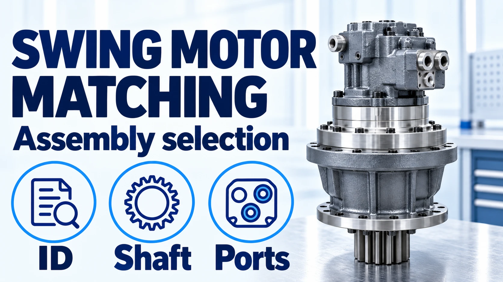
An incorrectly matched excavator swing motor can leave the machine waiting for another removal and refit. Match the hydraulic motor, swing gearbox and offered assembly scope against the machine serial, complete component codes and mating-interface drawings before ordering.
An excavator swing drive request needs a defined supply boundary: motor only, reduction gearbox only, or the combined assembly with its listed accessories. Record the motor-to-gearbox spline separately from the gearbox output pinion that meshes with the slew ring. Then compare the mounting interfaces, valve-block configuration, parking-brake controls and complete nameplate suffixes. Matching spline count or bolt holes alone leaves important fitment questions open. The comparison and editable RFQ record below help you put those questions into the quotation.
Scroll horizontally to view all columns.
| Input or item | Value or source to record | Why it matters |
|---|---|---|
| Machine and serial | Plate photo and serial-applicable parts-book reference | Selects the installed configuration |
| Motor and reducer identity | Complete numbers, suffixes and separate label photos | Keeps hydraulic and mechanical identities connected |
| Supply boundary | Motor, gearbox, or listed combined assembly | Makes quotations comparable |
| Mating interfaces | Drawing plus labelled measurements and units | Checks spline, flange, pilot and shaft projection |
| Valve and brake circuit | Port drawing, option code and machine schematic | Checks function as well as connection size |
Define what the swing-drive quotation includes
Ask the supplier to list the motor, reducer, output pinion, brake and valve items included in the offer. The word “assembly” alone does not settle that list. Start with the swing motor and swing-drive sourcing category, then specify the boundary for your request.
The hydraulic motor converts hydraulic input into shaft rotation. The reduction gearbox reduces speed and drives the output pinion. The pinion meshes with the large slew ring; the swing bearing matching guide covers that separate bearing and gear interface.
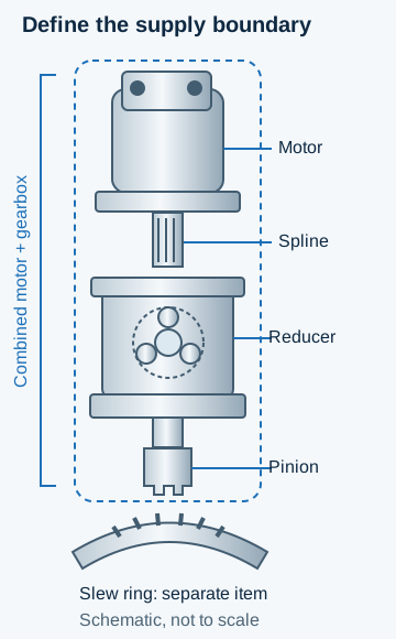
The motor-to-reducer spline and the output pinion are different interfaces. The combined supply boundary must be listed in the quote; the slew ring remains a separate item. Schematic, not to scale.
Scroll horizontally to view all columns.
| Requested scope | When to consider it | Evidence needed before choosing | Dominant Failure Mode & Prevention |
|---|---|---|---|
| Hydraulic motor only | Technician has assessed the retained gearbox and mating coupling as serviceable | Full motor code; spline and flange drawing; valve/brake configuration; retained reducer identity | An incompatible or worn coupling can compromise the replacement. Inspect the retained mating parts and compare the complete interface. |
| Reduction gearbox only | Technician has assessed the retained motor and controls as serviceable | Reducer code, ratio, motor interface, machine mounting and output-pinion drawing | A matching housing can conceal a different ratio or pinion. Compare the reduction and both mechanical interfaces. |
| Combined motor and gearbox | Both sections need replacement, or retaining either section needs further assessment | Complete combined code; machine mounting; pinion; hydraulic and brake ports; included-item list | A combined unit can still have the wrong valve option or pinion. Resolve the external interfaces and exclusions in writing. |
A symptom such as weak swing, rebound or leakage does not select one row by itself. Keep the technician's findings on the motor, gearbox, brake and control circuit with the request. This guide supports purchasing identification; use the applicable machine procedure for diagnosis and service work.
Keep the full nameplate code and the machine serial together
Transcribe every character on the motor and reducer labels, including suffixes, rather than sending only a familiar model-family name. In the OEM catalog reviewed for this guide, the ordering structure distinguishes motor size, valving, parking-brake provision and geared versions. A shared family designation therefore leaves configuration unresolved.
Photograph the complete unit first, then each label and visible interface. Keep an uncertain character as [?]; a casting mark may identify a housing rather than the orderable assembly. If a label is missing, combine the machine serial, parts-book figure/item and measured interfaces for part identification. Keep any documented supersession with the original number instead of silently replacing it in the request.
The part photography guide explains how to connect a close-up to the whole component. Label the photos “motor plate,” “reducer plate,” “motor shaft” and “output pinion” so the recipient can tell which interface each number describes.
Match spline geometry, flange and shaft engagement
Count the motor shaft's spline teeth and identify the mating reducer input separately. Equal tooth count is a screening result; module or diametral pitch, pressure angle, root form, fit specification and usable engagement still need comparison.
On removed, safely accessible hardware, mark a starting tooth and count around to that mark, then repeat the count. Record damage and uncertainty. Do not dismantle an installed assembly just to obtain a purchasing photo; use the workshop's approved procedure and the applicable drawing.
Matching boundary: a difference of one spline tooth rules out an unqualified direct-replacement claim. Hold the candidate for a documented corrected identification or approved supersession. Equal count does not release the candidate until the remaining drawing fields match.
For a standard metric involute spline, reference pitch diameter is d = m × z, where m is module in millimetres and z is tooth count. With hypothetical inputs, m = 2 mm and z = 16 give d = 2 × 16 = 32 mm; the same 16 teeth at m = 2.5 mm give d = 2.5 × 16 = 40 mm. The count is identical while the reference geometry differs.
Pitch diameter is not the outside diameter measured with a caliper. The ISO 4156-1:2021 public scope addresses straight, side-fitting involute splines; it does not establish which spline standard your excavator uses. Obtain the standard and complete callout from the actual drawing, including an imperial or other specification where applicable.
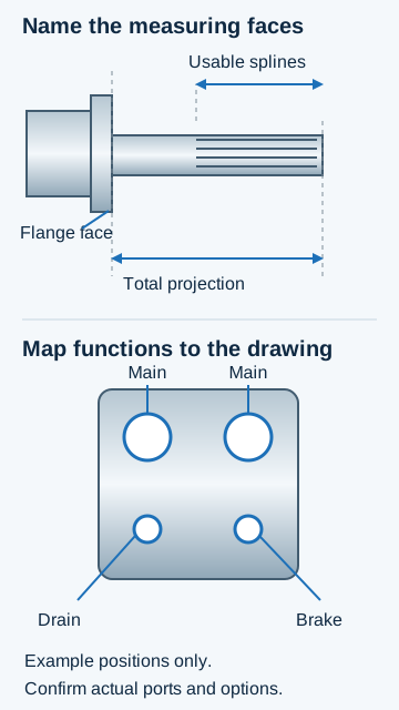
Measure from a named flange face and distinguish usable spline length from total shaft projection. Map each visible port to the actual circuit drawing; these example positions are not a connection layout.
Record the motor mounting-hole pattern, pilot diameter, seal arrangement, shaft projection from the mounting face and usable spline length. Compare the matching reducer depth and clearances against the drawing. A shaft that bottoms before the flange seats, or has insufficient specified engagement, requires the identity and dimensions to be resolved before acceptance; bolts are not a means of pulling a mismatched interface into place.
For a combined unit, also compare the machine mounting flange and the output pinion: tooth count, gear geometry, face width and position. Do not substitute the motor spline count for the pinion count on the RFQ.
Distinguish relief, anti-reaction and parking-brake functions
Identify the valve-block option and each port's function from the component and machine drawings. A similar-looking block, or matching thread size, does not confirm the internal functions or settings.
The reviewed swing-motor catalog describes relief and make-up valve arrangements, an optional anti-reaction valve and an optional parking-brake delay valve. These serve different purposes:
- Relief valving addresses pressure behaviour; make-up flow helps prevent cavitation under the documented circuit conditions.
- An anti-reaction valve addresses swing rebound or jerkiness as rotation stops. Its presence is a configuration question, not a substitute for a parking brake.
- The documented parking brake is a holding device. Its delay arrangement postpones application until the motor has stopped; it is not the dynamic braking function.
These are functional distinctions from a documented motor family. Confirm how the installed machine implements them before selecting a replacement. Do not transfer a pressure setting, delay or port designation from a different motor.
Scroll horizontally to view all columns.
| Circuit item | Record for the old unit and candidate | Difference to resolve |
|---|---|---|
| Main working ports | Port functions, thread/flange specification and orientation | Connections and circuit compatibility |
| Case drain | Identified drain port, routing requirements and applicable pressure limit source | Drain restriction or incorrect routing can damage seals; use the actual installation requirements |
| Make-up supply | Whether supplied internally or by the machine circuit, with schematic reference | Required inlet support under the specified operating conditions |
| Relief / anti-reaction options | Full block code, included valves and documented settings | Missing or different control function |
| Parking brake / delay | Brake provision, release connection, control arrangement and specification source | Incorrect release or application behaviour |
Ask for a marked port drawing and a list of included valve and brake parts. If a component will be transferred from the old motor, name it explicitly and have the workshop confirm its condition and compatibility. Leave unknown settings marked “to confirm”; do not copy a familiar value into an empty field.
Compare the same repair event, including repeat fitting
Compare quotations over the same repair event and downtime period, with identical scope assumptions. A lower motor-only line can leave gearbox inspection, accessory transfer or a second installation outside the offer.
Use repair-event cost = P + F + L + C + H × r, where P is the listed parts cost, F is freight, L is removal/refit labour, C is inspection and required companion work, H is non-overlapping downtime hours, and r is the site's downtime cost per hour. Keep labour cost and production loss separately defined to avoid counting the same loss twice.
Hypothetical planning inputs: 8 hours of repeat fitting versus 2 hours of pre-order identification produce a time difference of 8 − 2 = 6 hours. Its downtime value is 6 × r, using your site's hourly loss. Replace those assumptions with job records; the arithmetic does not establish which supply scope will be cheaper on your machine.
Record packing, freight, valve/brake inclusions, pinion scope, inspection evidence and warranty terms alongside the number and price. The sourcing and quotation process explains how the offered manufacturer, availability, fitment and commercial terms are confirmed.
What to send us
Send the identity, interface evidence and requested supply boundary together. HeavyPartsSource reviews part-identification and sourcing requests; confirm the offered manufacturer, fitment, included items, availability and terms in the written quotation.
Scroll horizontally to view all columns.
| Item | Why we need it | Example format |
|---|---|---|
| Machine identity | Connects the request to its serial-applicable reference | Make, full model, serial and plate photo |
| Motor and reducer numbers | Identifies both sections and options | Complete labels, suffixes and parts-book figure/item |
| Mechanical interfaces | Compares motor-to-reducer and reducer-to-machine fit | Drawing revision, spline callout/count, flange, pilot, projection and pinion record |
| Valve and brake configuration | Separates connections, controls and supplied accessories | Marked port photos plus schematic and setting-source references |
| Condition findings | Explains why a section is retained or replaced | Workshop report; inspection/test conditions and applicable manual reference |
| Requested scope and destination | Defines a comparable sourcing line | Motor/gearbox/combined unit; accessories, quantity and destination country |
Method and sources
Updated October 19, 2026. This guide combines published hydraulic swing-motor configuration guidance, spline terminology and a buyer matching record. The diagrams identify supply boundaries and recording references; they do not specify a particular excavator's construction or port positions. The cover depicts a generic swing-drive arrangement.
- Published swing-motor and geared-motor catalog, KPM1420, December 2014, printed pages 3–6 and 15–18: motor/reducer scope, ordering-code options, attached valves, parking-brake purpose and application conditions. Use the current serial-applicable drawing and manual for the installed unit's specifications.
- ISO 4156-1:2021 public scope and definitions, checked October 19, 2026: straight side-fit involute spline terminology and reference geometry. The public material supports the distinction between tooth count, module and fit; it is not a candidate's dimensional inspection report or certificate.
Numerical examples use stated hypothetical inputs. Application-specific tolerances, pressure settings, brake controls, installation and acceptance requirements must come from the applicable machine and component documents.