
Publisher: HeavyPartsSource
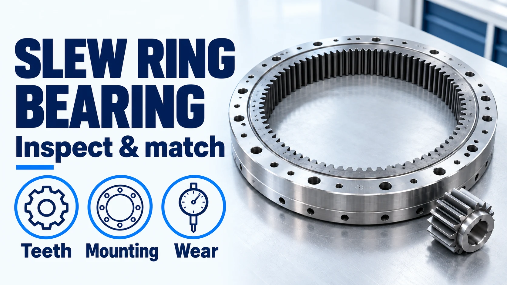
A misidentified excavator slew ring bearing can leave a machine dismantled while a replacement fails to fit. Inspect the swing bearing with the machine-specific procedure, then match the bearing, mounting pattern and swing-reducer pinion together.
For an excavator replacement, a slew ring bearing needs two records: a condition record that separates raceway movement from gear backlash and loose joints, and an identity record that connects the machine serial number to the bearing and pinion drawings. Tooth count and outside diameter help screen candidates; they do not establish compatibility. Use this guide to record measured values, their reference points and the outstanding drawing checks before comparing offers.
Scroll horizontally to view all columns.
| Input or item | Value or source to record | Why it matters |
|---|---|---|
| Machine and bearing identity | Serial plate, old bearing number, applicable parts-book revision | Selects the correct reference and serial range |
| Gear arrangement | Internal or external teeth; counted ring and pinion teeth | Locates the mesh and narrows the candidate |
| Gear geometry | Drawing module, pressure angle, profile shift and face width | Determines whether the gears can mesh correctly |
| Mounting interfaces | Separate inner/outer hole circles, hole counts, pilots and height | Checks both structures attached to the bearing |
| Wear assessment | Approved method, marked points, baseline and applicable limit | Makes readings comparable and actionable |
Separate bearing movement from swing-drive backlash
Locate the movement before ordering a bearing. The slew ring supports the rotating upper structure; the hydraulic swing motor and reduction gearbox drive its rotation through a pinion. A request for a swing motor or swing-drive assembly therefore has a different scope from a request for the large supporting ring bearing.
If the request concerns the drive rather than the supporting bearing, use the excavator swing motor and gearbox matching guide to separate the motor-to-reducer spline, output pinion and valve/brake configuration before comparing motor-only and combined-assembly offers.
The following observations guide the next inspection. They are not diagnoses from sound or movement alone.
Scroll horizontally to view all columns.
| Observation | Evidence to collect | Dominant Failure Mode & Prevention |
|---|---|---|
| Upper structure rocks relative to the lower structure | Technician's relative axial readings, marked positions, loading setup and baseline | Raceway wear can be confused with support deflection. Repeat the approved measurement near the raceway with the same references. |
| Rotational lost motion or knock when direction changes | Gear-tooth condition, pinion condition, measured tooth-flank clearance and contact pattern | Worn or incorrectly set mesh can remain after bearing replacement. Assess both mating gears and verify the specified adjustment. |
| Movement at a bolted interface | Fastener inspection and mounting-surface findings | A loose joint can distort the reading and damage the connection. Resolve the fastening/support condition under the machine procedure before interpreting wear. |
| Damaged seal or contaminated lubricant | Location photos, lubrication history and any lubricant-analysis report | Contamination can accompany raceway damage. Include seal and lubrication findings in the condition assessment. |
Record axial wear with the same measurement setup
Compare readings only when the method, gauge references, machine configuration and loading conditions match. Bearing manufacturers distinguish tilting-clearance measurement from axial-reduction measurement; their values and limits are not interchangeable.
Have the technician identify the applicable machine procedure before loading or moving the excavator for a measurement. This guide defines the record to retain; the machine manual defines the access, support and loading arrangements.
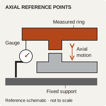
Record the gauge base and contact point. Measure close to the raceway to reduce the influence of structural deflection. Reference locations are schematic; use the machine's actual arrangement.
Retain the initial or commissioning reading, fixed measuring-point marks, gauge identification/resolution, machine hours, attachment configuration and the loading sequence used. Check the bearing fastening condition before repeating measurements. If the baseline is missing, record that gap and obtain an assessment against the applicable manual rather than treating today's total movement as wear accumulated since new.
For the same point and setup:
Wear increase Δ = current reading C − reference reading C₀.
Hypothetical record: C = 0.72 mm and C₀ = 0.40 mm, so Δ = 0.72 − 0.40 = 0.32 mm. This arithmetic shows the change only. It does not classify that bearing as serviceable or worn out.
Decision boundary: compare the quantity specified by the manual with its own limit L. If that quantity exceeds L, follow the prescribed withdrawal and repair decision. If the method or definition of L is unknown, obtain it before releasing the machine on the strength of a clearance reading. A limit for increase from baseline cannot be applied directly to total measured clearance.
Count ring teeth and match the reducer pinion
Count the actual ring teeth and the pinion teeth separately, then compare the complete gear callouts. Matching tooth count alone leaves module, pressure angle, profile shift, face width and working center distance unresolved.
On safely accessible removed hardware, mark one starting tooth, tally each tooth once and return to that mark. Repeat the count independently. Record a broken or missing tooth position explicitly so a damaged gap does not become a counting error. If installed teeth cannot be accessed safely, request the applicable drawing and a qualified inspection rather than estimating from a partial photograph.
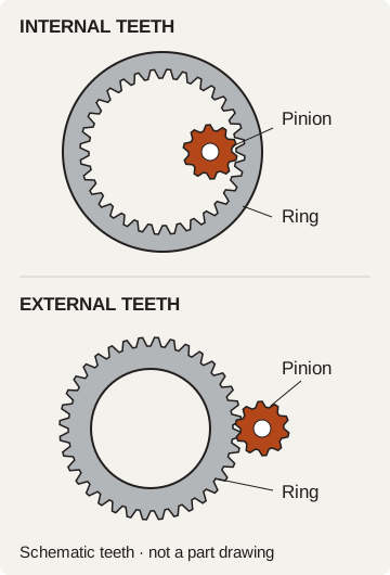
Internal and external teeth require different pinion locations. The drawn teeth explain the relationship; use counted teeth and the actual drawing for identification.
Matching rule: if the candidate ring tooth count differs from the verified reference by even one tooth, hold the substitution for documented engineering approval. A ring that bolts on can still have incompatible gearing. An exact tooth-count match is only one check in the full comparison.
For standard, unshifted spur gearing, reference pitch diameter d = m × z, where m is module in millimetres and z is tooth count. Center distance a is:
- Internal ring and pinion: a = m × (zᵣ − zₚ) / 2.
- External ring and pinion: a = m × (zᵣ + zₚ) / 2.
Hypothetical geometry with m = 8 mm, zᵣ = 100 and zₚ = 12 gives ring reference diameter dᵣ = 8 × 100 = 800 mm. Internal centers give a = 8 × (100 − 12) / 2 = 352 mm; external centers give a = 8 × (100 + 12) / 2 = 448 mm.
These are reference-geometry examples, not excavator specifications. Pitch diameter is not the ring's measured outside diameter. Profile-shifted or helical gears require their corresponding drawing calculations; do not derive a replacement module from a worn tooth-tip diameter and assume the fit.
Request the specified backlash measurement method and acceptance range for the actual bearing/pinion pair. Include any marked adjustment position or high-point instructions from that drawing, plus the pinion condition. Do not set tooth-flank clearance from the axial bearing-wear reading.
Measure both mounting circles, not just outside diameter
Record the inner-ring and outer-ring mounting interfaces as separate sets. Include hole count, center-circle diameter, hole or thread size, counterbore details, angular pattern and any offset between patterns. Also record ring height, locating pilots or shoulders, and which face each dimension references.
For N equally spaced holes and the center-to-center chord c between neighboring holes:
Bolt-circle diameter D = c / sin(180° / N).
Hypothetical check: N = 24 and c = 100 mm gives D = 100 / sin(7.5°) = 766.13 mm, rounded to two decimal places for the example. With an even, uniformly spaced pattern, truly opposite hole centers lie across D and provide a useful cross-check. Measure centers rather than outside edges or counterbore edges. For irregular spacing, use the drawing or coordinate measurements instead of this formula.
Scroll horizontally to view all columns.
| Interface record | Old bearing / verified drawing | Candidate offer |
|---|---|---|
| Inner mounting circle | Count; circle diameter; hole/thread and pattern | Same fields, with drawing revision |
| Outer mounting circle | Count; circle diameter; hole/thread and pattern | Same fields, with drawing revision |
| Cross-section and location | Height; pilot/shoulder diameters; referenced faces | Corresponding dimensions and tolerances |
| Lubrication and installation features | Fittings, passages and drawing orientation marks | Confirmed locations and access |
If a measured dimension falls outside the drawing tolerance, do not resolve it by forcing bolts into position. Resolve the measurement reference, drawing revision and candidate identity first. Keep photographs tied to individual dimensions using the part photography checklist.
Compare the whole repair event and the offered scope
Compare offers for the same repair event and downtime period. Specify whether each line covers the ring bearing, pinion, swing reducer, seals, fasteners or associated work. A bearing-only offer cannot be compared directly with an assembly offer that includes other items.
Use repair-event cost = parts + freight + removal/refit + inspection/adjustment + downtime hours × site downtime cost per hour. Keep downtime categories separate so waiting, planned lifting work and repeated installation are not counted twice.
A hypothetical planning comparison of 6 hours of repeat fitting versus 2 hours of pre-order identification has a net time difference of 6 − 2 = 4 hours. Its monetary effect is 4 × your site's hourly downtime cost, before any other scope differences. Replace both assumptions with your own job records; this example assigns no price or guaranteed saving.
A damaged mating pinion or unresolved mounting condition belongs in the same request as the ring. Use the swing-drive category to distinguish motor, reducer and combined-assembly requirements, and the sourcing and quotation process to check how offered scope and terms are confirmed.
What to send us
Send the machine identity, condition record and matching evidence together. HeavyPartsSource can review the identification and sourcing request; confirm the offered manufacturer, fitment, included items, availability and commercial terms in the written quotation.
Scroll horizontally to view all columns.
| Item | Why we need it | Example format |
|---|---|---|
| Machine serial and old bearing identification | Connects the request to the applicable reference | Plate photo plus complete number as found |
| Parts-book and bearing drawing reference | Resolves revisions, interfaces and gear specification | Document title/revision, figure and item |
| Ring and pinion record | Checks the mating pair | Internal/external teeth, separate counts, gear callouts and pinion code |
| Mounting dimensions | Compares both mounting interfaces | Inner and outer records with units and annotated photos |
| Technician's condition report | Separates bearing wear, mesh and joint findings | Method, point, readings, baseline, applicable limit and source |
| Scope, quantity and destination | Defines a comparable offer | Bearing only or listed companion items; quantity and country |
If the old number is unreadable, include the uncertainty and use our part identification service with the drawing and photo evidence you have.
Method and sources
Updated October 19, 2026. This guide combines published bearing-inspection methods with standard spur-gear geometry and a buyer handoff record. Application-specific machine instructions govern loading, service limits, installation and adjustment.
- Bearing-manufacturer Installation, Lubrication, Maintenance / Bearing Inspection, June 2024, printed pages 12–15: measurement references, baseline comparison and method-specific wear assessment. The manufacturer's inspection guidance also separates gear, pinion, seal and lubrication checks.
- Published Calculation of Gear Dimensions, standard spur and internal-gear sections: reference diameters, center-distance relationships and profile-shift conditions. Numerical examples above use explicitly hypothetical inputs.
- ISO 1328-1:2013 official abstract, checked October 19, 2026: tooth-flank tolerance classification for cylindrical involute gears. It supplies a specification reference when a drawing calls for it; it does not establish an excavator bearing-wear limit or certify an offered part.
Retain the machine-specific drawing, inspection procedure and applicable limit alongside the completed record. Those documents determine which values can be accepted for your excavator.