
Publisher: HeavyPartsSource
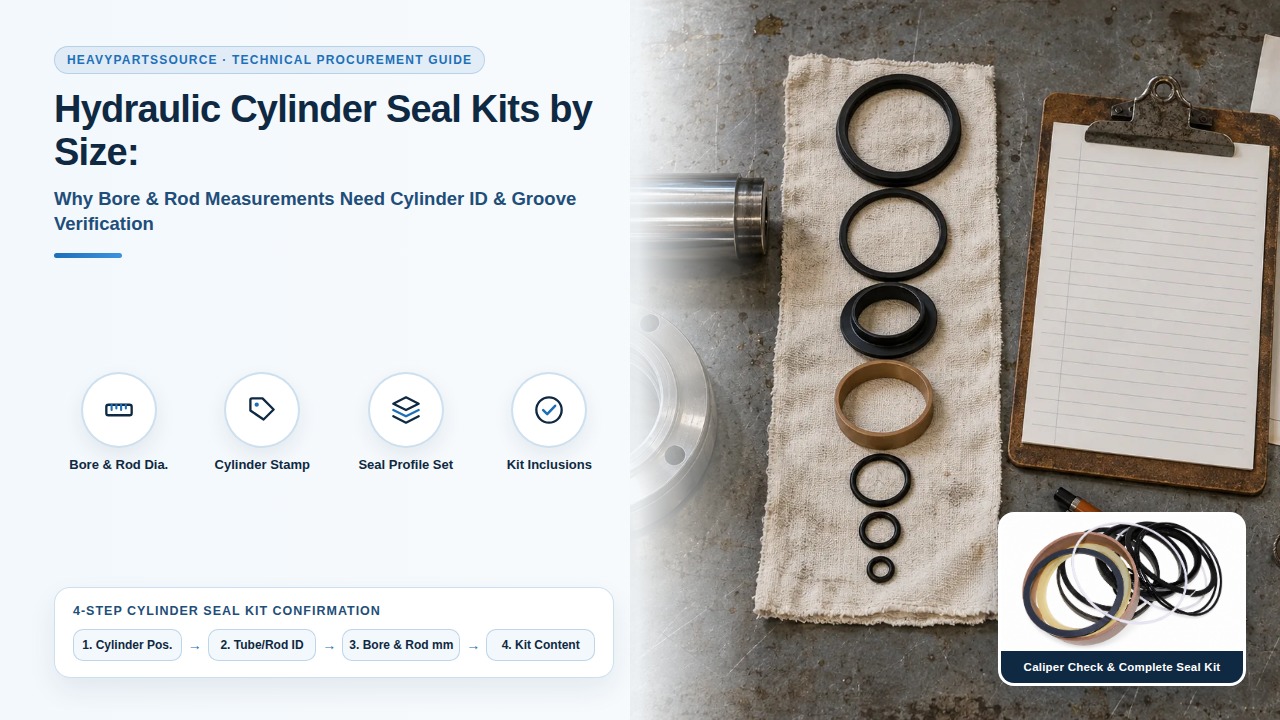
Ordering a hydraulic cylinder seal kit by nominal bore and rod diameter alone causes housing groove mismatch, high-pressure extrusion, internal bypass leakage, and repeat machine downtime. Across heavy mobile equipment from SANY, XCMG, Zoomlion, and LiuGong, two cylinders sharing an identical 140 mm tube bore and 100 mm chrome rod frequently use incompatible rod housing throat depths (ISO 5597:2018 100 x 115 x 12.5 mm versus 100 x 120 x 15 mm), different wiper arrangements (ISO 6195:2002 snap-in Type C versus press-fit metallic Type B), or mid-series vendor changes between KYB, Hengli, and Jiangsu Changheng cylinder assemblies.
For 20-ton to 50-ton hydraulic excavators operating at 31.4 to 34.3 MPa (35 MPa attachment relief), verify seven physical inputs before purchasing a replacement seal kit: cylinder assembly part number from the barrel nameplate, machine model and 17-character PIN/serial number, cylinder function (boom, arm, bucket, outrigger, or steering), hard-chrome rod outside diameter (d), honed barrel bore inside diameter (D), metallic groove inside/outside diameters plus axial widths (L), and seal profile architecture (buffer + U-cup + wiper stack).
Scroll horizontally to view all columns.
| Verification Input | How to Measure or Locate | Governing Standard / Tolerance | Failure Risk if Skipped |
|---|---|---|---|
| Cylinder Assembly P/N | Stamped on barrel head flange or welded aluminum tag (e.g., SANY B229900001053 or Hengli code) | OEM Engineering Bill of Materials (BOM) | Wrong sub-supplier kit (Hengli vs. KYB internal gland revisions) |
Chrome Rod OD (d) | Outside micrometer or 0.02 mm vernier caliper on unworn chrome shaft section | ISO 3320 metric series; shaft tolerance f8 or f7 | Rod U-cup and buffer ring radial interference loss or rod scoring |
Barrel Bore ID (D) | Telescoping bore gauge + micrometer below top port entry, or piston OD across wear ring land | ISO 3320 metric series; bore tolerance H8 or H9 | Piston seal (SPGW/SPGO) blow-by and cylinder drift under load |
Rod Seal Housing (d1 x D1 x L1) | Measure gland throat ID (d1), groove root ID (D1), and axial width (L1) with internal/depth calipers | ISO 5597:2018 (H9 groove OD, 0 / +0.25 mm width) | Radial cross-section mismatch (7.5 mm vs. 10 mm radial section) |
Wiper Housing (d1 x D2 x L2) | Inspect snap-in recessed groove vs. open counterbore (Type A/B press-fit vs. Type C/D snap-in) | ISO 6195:2002 Types A, B, C, and D | Wiper ejection on retraction or external dirt ingestion into gland |
Piston Seal Groove (D x d2 x L3) | Measure piston land OD, seal groove root OD (d2), and axial width (L3) | ISO 7425-1:2021 (h9 groove root, +0.2 / +0.4 mm width) | Axial shuttle hammering of PTFE slide ring or O-ring energizing failure |
| Guide / Wear Ring Grooves | Measure phenolic or bronze-PTFE strip thickness (2.5 mm, 3.0 mm, or 4.0 mm) and axial width (9.5 to 25 mm) | ISO 10766:2014 (+0.20 / +0.40 mm groove width tolerance) | Metal-to-metal piston/gland seizure and radial extrusion gap growth |
Engineering Rule-of-Thumb (Why Never to Measure Old Elastomer Rings): Never size a replacement seal kit by measuring extracted polyurethane or nitrile rings with calipers. Service temperatures above 80 degC, hydraulic fluid swelling, and 15% to 25% permanent compression set distort extracted polymer lips by 0.8 mm to 2.2 mm. Always measure the machined metal housing grooves on the cylinder gland and piston, or cross-reference the stamped cylinder assembly code.
1. Two Valid Paths to Identify a Hydraulic Cylinder Seal Kit
Maintenance and procurement teams have two reliable workflows to specify a heavy-equipment seal kit:
- Path A — Nameplate & OEM Catalog Cross-Reference (Preferred when cylinder is still assembled): Read the complete cylinder assembly part number stamped into the cylinder barrel base cap, rod head flange, or attached nameplate, paired with the machine model and 17-character serial number (PIN). Because Chinese OEMs (SANY, XCMG, Zoomlion, LiuGong) frequently dual-source complete hydraulic cylinders from domestic tier-1 manufacturers (Hengli Hydraulic, Zhongchuan) and Japanese joint ventures (KYB, Nabtesco), the cylinder assembly number—not just the excavator model—dictates which internal gland and piston revision is installed.
- Path B — Metal Groove Metrology (Mandatory when the nameplate is missing, painted over, or the cylinder has been aftermarket-rebuilt): Once the cylinder is torn down on the bench, clean all oil from the gland (head bushing) and piston, then measure the six critical metal dimensions: Rod OD (
d), Bore ID (D), groove root diameter, groove throat diameter, axial groove width (L), and wear-ring slot dimensions.
If your crew is already troubleshooting slow boom drift or external rod weeping alongside main hydraulic pump pressure loss, verify whether the issue originates in the cylinder seals or the main pump regulator using our Replacement Hydraulic Pump Verification Guide.
2. How to Measure Cylinder Bore, Rod, and Metal Seal Grooves
Accurate seal sizing requires measuring the rigid steel or ductile-iron components that constrain the seal. Use a calibrated outside micrometer (0.01 mm resolution), an inside groove caliper or telescoping gauge set, and a depth micrometer.
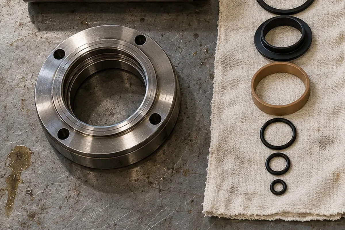
Figure 1: Inspecting the machined internal grooves of a disassembled hydraulic cylinder gland head (buffer ring groove, primary rod U-cup groove, snap-in wiper recess, and phenolic wear ring slots) prior to ordering a replacement seal kit.
Step 1: Measure Hard-Chrome Rod Diameter (d)
Wipe the chrome-plated piston rod clean and measure its outside diameter (d) in at least two perpendicular planes (X and Y axes) across an unworn section near the rod eye, plus two locations in the mid-stroke working zone.
- Standard Metric Rod Increments (
ISO 3320): Heavy equipment cylinders almost universally follow standard metric rod diameters:40, 45, 50, 55, 60, 63, 65, 70, 75, 80, 85, 90, 95, 100, 105, 110, 115, 120, 125, 130, 140, 150, 160, 180 mm. - Machining Tolerance & Surface Roughness: Standard rod machining tolerance is
f8orf7(for example, a nominal100.00 mmrod measures99.928 mmto99.964 mmunderf7). Chrome surface finish on the running surface must remain withinRa 0.10 to 0.30 um(Rz 1.0 to 2.5 um). If longitudinal rock scoring exceeds0.05 mmdepth or chrome flaking is visible, re-chroming or rod replacement is required—installing a new polyurethane U-cup over scored chrome will shred the dynamic lip within 50 operating hours.
Step 2: Measure Cylinder Barrel Bore (D)
Do not measure the cylinder barrel right at the threaded or bolted mouth of the tube, where wrench burrs, tapered entry chamfers, or flange distortion skew caliper jaws.
- Direct Bore Measurement: Insert a telescoping bore gauge or three-point internal micrometer
100 mmto150 mmpast the head threads into the honed working section of the barrel. Check for barrel ovality (ballooning) at mid-stroke on high-hour boom and bucket cylinders; ovality exceeding0.08 mmon a140 mmbore reduces piston seal contact pressure and causes high-pressure bypass. - Piston Proxy Measurement: If the barrel is still mounted on the excavator boom structure, measure the outside diameter of the steel piston across the wear-ring land and add twice the radial clearance (
typically +0.50 mm to +0.80 mm), rounding to the nearestISO 3320standard bore size (63, 70, 80, 90, 95, 100, 105, 110, 115, 120, 125, 130, 135, 140, 145, 150, 160, 170, 180, 200 mm). - Honed Bore Surface Finish: The barrel ID (
H8orH9tolerance) should maintain a cross-hatched honed finish ofRa 0.10 to 0.40 um(Rz 1.6 to 3.2 um) to retain a microscopic lubricating oil film for PTFE piston slide rings.
Step 3: Measure Rod Gland and Piston Groove Geometry
Every hydraulic seal groove is defined by three metal coordinates:
- Inner Diameter (
d1ord2): For a rod gland,d1is the rod diameter (d). For a piston,d2is the machined bottom (root) diameter of the piston seal groove. - Outer Diameter (
D1orD): For a rod gland,D1is the machined internal bottom (root) diameter of the groove inside the gland head. For a piston,Dis the cylinder bore ID. - Axial Groove Width (
L): The parallel distance between the vertical metal groove walls, measured with a depth micrometer or inside groove vernier jaw.
Compute the nominal radial cross-section (S) of any rod or piston groove using the metal housing formula:
Rod Groove Radial Cross-Section (S_rod)    = (D1 - d) / 2
Piston Groove Radial Cross-Section (S_pis) = (D - d2) / 2
For example, if your excavator bucket cylinder rod measures d = 90.00 mm and the primary rod U-cup groove inside the gland measures D1 = 105.00 mm with an axial groove width L1 = 12.50 mm, the radial cross-section is (105 - 90) / 2 = 7.50 mm. The housing callout is 90 x 105 x 12.5 mm (ISO 5597 medium series), which takes a nominal 90 x 105 x 11.4 mm or 90 x 105 x 11.5 mm rod U-cup (1.0 mm axial clearance inside the 12.5 mm groove).
Selection Takeaway: Always record the metal groove width (L_groove) and specify whether your measurement is the metal groove or the seal ring height (h_seal). A rod U-cup always sits 0.8 mm to 1.5 mm narrower than its metal groove width L so hydraulic oil can enter behind the lip and energize the seal without axial binding.
3. ISO Housing Standards for Heavy Equipment Cylinders
International cylinder manufacturers design gland and piston housings around four core ISO dimensional standards. Understanding these tables lets you immediately spot whether a groove is standard metric or proprietary.
Scroll horizontally to view all columns.
| ISO Standard | Seal Position | Key Housing Parameters & Tolerances | Typical Heavy-Equipment Seal Profiles |
|---|---|---|---|
ISO 5597:2018 | Single-acting rod seals & buffer rings (reciprocating rod housings) | Groove OD D1 tolerance H9; groove width L1 tolerance 0 / +0.25 mm; lead-in chamfer 15 deg to 30 deg | IDI, IUH, KYB U-cups; HBY, HBTS step-type buffer rings with back-up ring |
ISO 6195:2002 | Reciprocating rod wiper (scraper) housings | Type A: Press-fit outer metal case (H8 housing bore)Type B: Press-fit slotted heel Type C: Snap-in elastomer/PU single or double lip Type D: Snap-in PTFE/elastomer energized wiper | DKB, DKBI, DSI (metal-cased press-fit Type A/B); DHS, LBH, DLI (snap-in Type C) |
ISO 7425-1:2021 | Elastomer-energized plastic-faced piston seal housings | Groove root diameter d1 tolerance h9; bore D tolerance H9; axial groove width L tolerance +0.2 / +0.4 mm | SPGW, SPGO, OK, KDAS, DAS heavy-duty compact piston seals; Glyd Ring (PGM) |
ISO 10766:2014 | Rectangular piston & rod guide / wear ring housings | Nominal radial thicknesses 2.5 mm, 3.0 mm, 4.0 mm; axial groove width tolerance +0.20 / +0.40 mm | Phenolic resin cotton fabric (WR, KZT), glass/bronze-filled PTFE guide strips (GP, GR), polyamide (PA66) rings |
Standard Metric Rod & Piston Housing Reference Table (63 mm to 180 mm)
The table below compiles standard metric housing dimensions across common 6-ton to 50-ton excavator cylinder sizes (ISO 5597, ISO 6195, ISO 7425-1, and ISO 10766):
Scroll horizontally to view all columns.
Cylinder Bore D (mm) | Rod OD d (mm) | Rod U-Cup Housing d x D1 x L1 (ISO 5597) | Rod Buffer Groove d x D_buf x L_buf | Wiper Groove d x D2 x L2 (ISO 6195) | Piston Seal Housing D x d2 x L3 (ISO 7425-1 / SPGW) | Guide Ring Thickness x Width (ISO 10766) |
|---|---|---|---|---|---|---|
| 80 mm | 55 mm | 55 x 65 x 10.0 or 55 x 70 x 12.5 | 55 x 70.5 x 6.3 | 55 x 63 x 5 / 8 (LBH) or 55 x 67 x 7 / 10 (DKB) | 80 x 64.5 x 6.3 (SPGO) or 80 x 62 x 22.4 (SPGW) | 2.5 x 9.7 mm or 2.5 x 15.0 mm |
| 95 mm | 65 mm | 65 x 77.5 x 10.0 or 65 x 80 x 12.5 | 65 x 80.5 x 6.3 | 65 x 73 x 5 / 8 (LBH) or 65 x 77 x 7 / 10 (DKB) | 95 x 75 x 22.4 (SPGW) | 2.5 x 15.0 mm or 3.0 x 15.0 mm |
| 105 mm | 75 mm | 75 x 90 x 12.5 | 75 x 90.5 x 6.3 | 75 x 83 x 5 / 8 or 75 x 87 x 7 / 10 (DKB) | 105 x 85 x 22.4 (SPGW) | 2.5 x 15.0 mm or 3.0 x 15.0 mm |
| 115 mm | 80 mm | 80 x 95 x 12.5 | 80 x 95.5 x 6.3 | 80 x 88 x 5 / 8 or 80 x 92 x 7 / 10 (DKB) | 115 x 95 x 22.4 (SPGW) | 3.0 x 15.0 mm or 3.0 x 20.0 mm |
| 120 mm | 85 mm | 85 x 100 x 12.5 | 85 x 100.5 x 6.3 | 85 x 97 x 7 / 10 (DKB) or 85 x 95 x 6 / 9 | 120 x 100 x 22.4 (SPGW) | 3.0 x 20.0 mm |
| 125 mm | 90 mm | 90 x 105 x 12.5 | 90 x 105.5 x 6.3 | 90 x 102 x 7 / 10 (DKB) or 90 x 100 x 6 / 9 | 125 x 105 x 22.4 (SPGW) | 3.0 x 20.0 mm or 3.0 x 25.0 mm |
| 135 mm | 95 mm | 95 x 110 x 12.5 | 95 x 110.5 x 6.3 or 95 x 115 x 8.0 | 95 x 107 x 7 / 10 (DKB) or 95 x 109 x 8 / 11 | 135 x 115 x 22.4 (SPGW) | 3.0 x 25.0 mm |
| 140 mm | 100 mm | 100 x 115 x 12.5 or 100 x 120 x 15.0 | 100 x 115.5 x 6.3 or 100 x 121 x 8.0 | 100 x 114 x 8 / 11 (DKB) or 100 x 110 x 6 / 9 | 140 x 115 x 25.4 (SPGW) | 3.0 x 25.0 mm or 4.0 x 25.0 mm |
| 150 mm | 105 mm | 105 x 120 x 12.5 or 105 x 125 x 15.0 | 105 x 120.5 x 6.3 or 105 x 126 x 8.0 | 105 x 119 x 8 / 11 (DKB) | 150 x 125 x 25.4 (SPGW) | 3.0 x 25.0 mm or 4.0 x 25.0 mm |
| 160 mm | 110 mm | 110 x 125 x 12.5 or 110 x 130 x 15.0 | 110 x 125.5 x 6.3 or 110 x 131 x 8.0 | 110 x 124 x 8 / 11 (DKB) | 160 x 135 x 25.4 (SPGW) | 4.0 x 25.0 mm |
| 170 mm | 120 mm | 120 x 135 x 12.5 or 120 x 140 x 15.0 | 120 x 141 x 8.0 | 120 x 134 x 8 / 11 (DKB) | 170 x 145 x 25.4 (SPGW) | 4.0 x 25.0 mm |
4. Dissecting a Heavy-Duty Excavator Cylinder Seal Architecture
A modern excavator boom, arm, or bucket cylinder operating at 31.4 to 34.3 MPa (35 MPa attachment overload relief) cannot survive with a single elastomeric U-cup. Instead, the cylinder uses a tandem pressure-staged sealing system inside both the gland head and the piston.
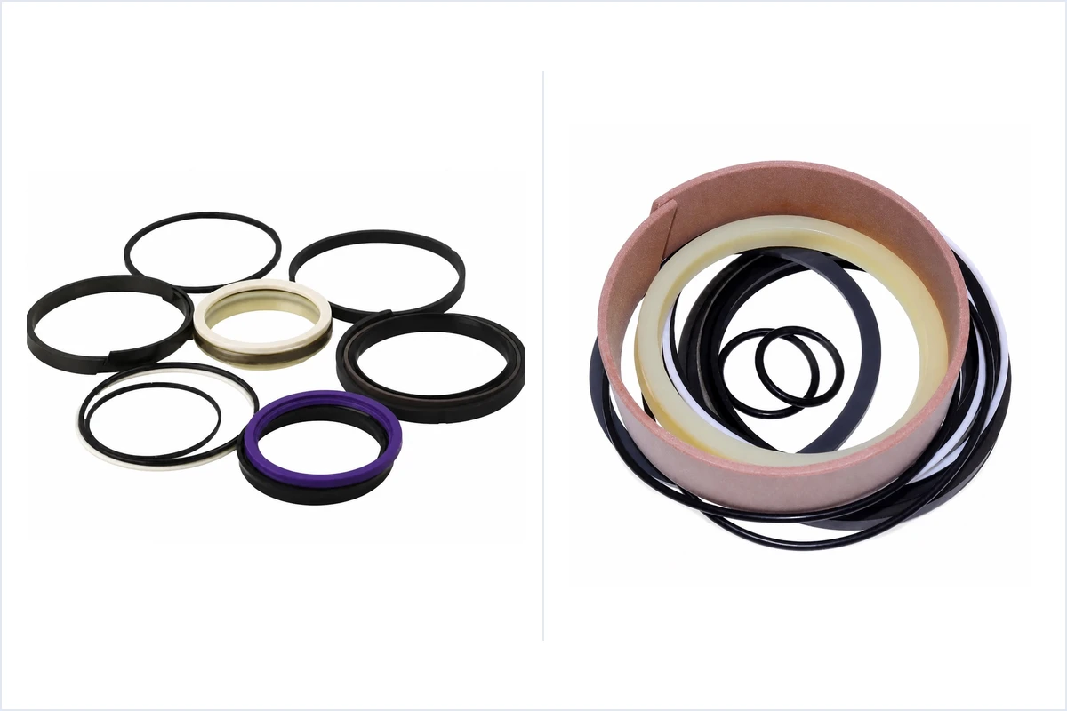
Figure 2: Complete heavy-duty excavator hydraulic cylinder seal kit profiles on the inspection bench—comparing multi-piece PTFE/bronze piston seal assemblies (SPGW), high-tear polyurethane primary rod U-cups (IDI), step-type pressure buffer rings (HBY), metal-cased double-lip scrapers (DKB), and phenolic resin fabric guide rings.
Inside the Rod Gland (From High-Pressure Oil Chamber to Atmosphere)
- Rod Guide / Wear Rings (
1to3rings,WR/KZT): Positioned inboard of or flanking the seals, phenolic resin-impregnated cotton fabric or bronze-filled PTFE wear strips absorb side-loads when bucket linkages articulate. By preventing metal-to-metal contact between the chrome rod and ductile-iron gland, wear rings preserve a tight radial extrusion gap (e) at the seal heels. - Primary Pressure Buffer Seal (
HBY/HBTS): Installed directly facing the rod-end oil chamber. During bucket digging or boom-lowering pressure spikes (up to 40+ MPatransient shock), the step-molded urethane or bronze-PTFE buffer ring absorbs shock pressures and vents trapped inter-seal oil back into the cylinder when rod-end pressure drops—preventing "pressure trapping" between the buffer ring and primary U-cup. - Primary Rod Seal (
IDI/IUH/U-Cupwith Polyacetal Back-Up Ring): A high-modulus thermoplastic polyurethane (TPU,93to95 Shore A) asymmetrical lip seal that wipes the remaining micro-film of hydraulic oil off the extending rod. In34.3 MPaexcavators, the primaryIDIU-cup relies on a contoured polyacetal (POM) anti-extrusion back-up ring seated in its heel. - Rod Wiper / Scraper (
DKB/DKBI/LBH): Installed at the outermost groove of the gland. On excavator bucket and arm cylinders exposed to abrasive silica mud, rock dust, and frost, OEMs typically specify a press-fit metal-cased NBR or polyurethane double-lip wiper (DKB/DKBI,ISO 6195 Type A) rather than a soft snap-in wiper.
Inside the Piston Assembly (Double-Acting Pressure Separation)
- Heavy-Duty 4-Piece Piston Seal (
SPGW/OK/KDAS): Standard on excavator boom, arm, and bucket pistons. AnSPGWassembly combines:- One bronze-filled PTFE or glass/MoS2-filled PTFE outer slide ring that contacts the honed barrel bore with ultra-low breakaway friction (
no stick-slip), - One rectangular NBR or FKM elastomer energizer ring underneath that provides radial contact force at zero pressure, and
- Two notched polyacetal (
POM) or polyamide (PA66) L-shaped anti-extrusion rings that flank the slide ring and bridge the radial clearance gap between the piston OD and barrel bore.
- One bronze-filled PTFE or glass/MoS2-filled PTFE outer slide ring that contacts the honed barrel bore with ultra-low breakaway friction (
- Piston Guide / Wear Rings (
2or3rings): Wide phenolic-cotton fabric strips (20 mmor25 mmwide x3.0 mmor4.0 mmthick) flanking the centerSPGWpiston seal to support the heavy piston mass and side loads. - Contamination Catch / Cushion Rings (
RYT/ Cast-Iron Rings): Many SANY and KYB excavator pistons include narrow stepped resin rings (RYT) at the outermost edges of the piston to trap metal burrs or weld spatter before debris can score the mainSPGWPTFE slide ring, plus bronze or cast-iron cushion sleeves that meter oil flow at the end of the stroke. - Static Head & Rod Piston O-Rings + Back-Up Rings: High-durometer
NBR 90 Shore Astatic O-rings paired with contouredPTFEorPOMback-up rings seal the static thread/spigot joint between the cylinder gland head and barrel tube, and between the piston bore and chrome rod shaft.
5. Seal Material Engineering & Radial Extrusion Clearance Limits
Selecting the right dimensional kit in a low-grade elastomer compound leads to premature lip chunking, thermal hardening, or high-pressure extrusion within months.
Hydraulic Seal Compound Selection Matrix
Scroll horizontally to view all columns.
| Material Code | Chemical Family & Hardness | Continuous Operating Temp | Max Pressure (with Back-Up) | Primary Cylinder Role & Application Notes |
|---|---|---|---|---|
TPU / H-PU (AU/EU) | Thermoplastic / Hydrolysis-Resistant Polyurethane (93–95 Shore A) | -30 degC to +105 degC (+110 degC for H-PU) | 35 to 40 MPa | Primary Rod U-Cups (IDI), Buffer Rings (HBY), Wipers (LBH). Highest tear strength (>80 kN/m) and abrasion resistance. Standard ester TPU degrades above 80 degC in water-glycol (HFC) or wet tropical environments; specify hydrolysis-resistant H-PU for high-duty cycle mining/breaker excavators. |
NBR 70 / 90 | Nitrile Butadiene Rubber (70 or 90 Shore A) | -30 degC to +100 degC (+120 degC intermittent) | 25 MPa (40 MPa with POM back-up) | Static Gland O-Rings (90 Shore A), Piston Energizer Rings (70 Shore A), Metal-Cased Wiper Lips (DKB). Excellent mineral oil (ISO VG 46 / VG 68) compatibility and low compression set at moderate temperatures. |
HNBR | Hydrogenated Nitrile Rubber (85–90 Shore A) | -30 degC to +140 degC | 35 to 40 MPa | High-Temp Static O-Rings & Energizers. Specified when continuous hydraulic oil temperatures exceed 95 degC (heavy hydraulic breaker attachments, continuous mulching, or desert ambient duty). |
FKM (Viton) | Fluoroelastomer (80–90 Shore A) | -15 degC to +200 degC | 35 to 40 MPa | Extreme-Heat & Synthetic Fluid Applications. Mandatory for steel-mill slag handling, kiln loaders, or fire-resistant phosphate ester (HFDR) fluids. Note poor low-temperature flexibility below -15 degC. |
PTFE + 40% Bronze / Glass+MoS2 | Filled Polytetrafluoroethylene | -55 degC to +200 degC | 40 to 50 MPa | Piston Slide Rings (SPGW/SPGO) & High-Speed Buffer Rings (HBTS). Zero stick-slip, ultra-low friction (mu = 0.05 to 0.08), and chemical inertness. Requires an elastomer O-ring energizer because PTFE lacks elastic memory. |
POM / PA66 | Polyacetal / Glass-Stabilized Polyamide | -40 degC to +110 degC | 45+ MPa | Anti-Extrusion Back-Up Rings. Seated on the low-pressure heel of rod U-cups, static gland O-rings, and SPGW piston seals to bridge the metal clearance gap. |
PF (Phenolic Fabric) | Phenolic Resin-Impregnated Woven Cotton | -40 degC to +120 degC | Compressive load 250 to 300 N/mm2 | Piston & Rod Guide / Wear Rings (WR/KZT). Absorbs radial side loads (60 to 80 N/mm2 continuous design bearing stress) without galling chrome rods or honed steel barrels. |
Calculating Maximum Allowable Radial Extrusion Gap (e_max)
High-pressure seal extrusion occurs when hydraulic pressure (P) forces the low-pressure heel of the seal into the radial clearance gap (e) between the moving rod (d) and the stationary gland throat bore (d_throat), or between the piston land OD and barrel bore (D).
Because non-metallic wear rings compress slightly under side load (Delta_w), the worst-case eccentric radial extrusion gap occurs on the side opposite the side load:
Maximum Eccentric Radial Gap (e_max) = (D_throat_max - d_rod_min) + Delta_w
To prevent seal heel nibbling and catastrophic blow-out, verify that your gland throat and piston clearances stay within these maximum radial gap limits:
Scroll horizontally to view all columns.
| Seal / Back-Up Architecture | At 16 MPa (2,300 psi) | At 25 MPa (3,600 psi) | At 35 MPa (5,000 psi) | At 42 MPa (6,000 psi Peak Shock) |
|---|---|---|---|---|
Unbacked NBR 70 Shore A O-Ring | 0.10 mm | Not recommended (use back-up) | Extrudes immediately | Extrudes immediately |
Unbacked NBR 90 Shore A O-Ring | 0.20 mm | 0.10 mm | 0.05 mm | Requires back-up ring |
Unbacked TPU 93–95 Shore A Rod U-Cup | 0.40 mm | 0.25 mm | 0.15 mm | 0.10 mm |
Bronze-PTFE Slide Ring (SPGO / Glyd Ring) | 0.50 mm | 0.40 mm | 0.30 mm | 0.20 mm |
Seal + POM / PA66 Anti-Extrusion Back-Up (SPGW / Backed IDI) | 0.70 mm | 0.60 mm | 0.50 mm | 0.35 mm |
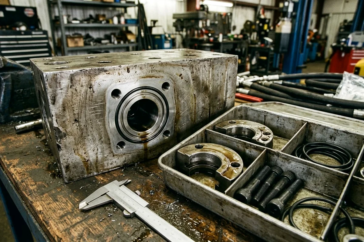
Figure 3: Verifying machined counterbore groove depth and seal cross-section with a vernier caliper prior to installation—ensuring proper axial compression (15% to 25% static squeeze) and zero extrusion clearance under high pressure.
Engineering Rule-of-Thumb (Why You Must Replace Wear Rings at Every Rebuild): Reusing worn phenolic guide rings (WR) that have thinned by just 0.25 mm allows the piston or chrome rod to shift radially under boom or bucket side-loads. That 0.25 mm shift opens the opposite-side radial extrusion gap (e_max) past 0.50 mm, causing a brand-new SPGW piston seal or IDI rod U-cup to extrude and shear within days of reassembly.
6. Reference Bore & Rod Sizing Across Popular Excavator Cylinders
Use the table below as a sanity check when identifying boom, arm (stick), and bucket cylinders on common 6-ton to 36-ton excavators. Always confirm against the cylinder barrel nameplate and serial number break before ordering, as OEMs update bore/rod pairings across Pro, Super, and H-series generations.
Scroll horizontally to view all columns.
| Machine Class & Representative Models | Cylinder Function | Typical Bore D x Rod d (mm) | Operating Relief Pressure | Common OEM Kit / Cylinder P/N Examples & Sub-Supplier Notes |
|---|---|---|---|---|
| 6-Ton Compact Excavator (SANY SY55C / SY60C, XCMG XE60D) | Boom Arm (Stick) Bucket Dozer Blade | 105 x 60 mm (or 100 x 55 mm)90 x 55 mm (or 85 x 55 mm)80 x 50 mm110 x 60 mm | 24.5 MPa (245 bar) | Compact cylinders often use 1-piece SPGO piston seals on blade cylinders and SPGW on boom/arm/bucket. |
| 13–14 Ton Mid-Size Excavator (SANY SY135C, XCMG XE135D, LiuGong 915E) | Boom Arm (Stick) Bucket | 100 x 70 mm (or 105 x 70 mm)115 x 80 mm95 x 65 mm (or 100 x 70 mm) | 31.4 to 34.3 MPa | SANY SY135C uses Hengli and SANY-in-house cylinders; check whether rod wiper is DKB press-fit or LBH snap-in. |
| 20–21 Ton Crawler Excavator (SANY SY215C, XCMG XE215D, Zoomlion ZE215E, LiuGong 920E) | Boom (x2)Arm / Stick ( x1)Bucket ( x1) | 120 x 85 mm135 x 95 mm115 x 80 mm (or 120 x 85 mm) | 31.4 MPa normal / 34.3 MPa power boost | Representative SANY SY215C seal kit references: 60210119, 60250669, B229900000492. Verify KYB vs. Hengli cylinder nameplate before ordering. |
| 33–38 Ton Heavy Excavator (SANY SY335C / SY365H, XCMG XE370D, LiuGong 936E) | Boom (x2)Arm / Stick ( x1)Bucket ( x1) | 140 x 100 mm (or 150 x 105 mm)160 x 110 mm (or 170 x 120 mm)140 x 100 mm (or 150 x 100 mm) | 31.4 to 34.3 MPa (35+ MPa breaker/heavy digging) | Representative SANY SY335C/SY365H references: 60114860, 60114861, 60246024, 60013712. Heavy H-series bucket cylinders add wider 4.0 x 25 mm phenolic wear rings. |
You can browse stocked seal kits and hydraulic cylinder components directly in our Hydraulic Seal Kits Catalog, filter active part numbers in the Seal & Gasket Parts Directory, or explore complete SANY Hydraulic System Assemblies.
7. Field Failure Diagnostics & Reassembly Best Practices
Before installing a new seal kit, inspect the failed seals removed during teardown. The failure pattern on the old polymer rings reveals mechanical root causes that must be corrected before reassembly:
Scroll horizontally to view all columns.
| Visual Failure Symptom on Removed Seal | Root Mechanical Cause | Corrective Action During Cylinder Rebuild |
|---|---|---|
Feathered or nibbled heel on low-pressure side of IDI rod U-cup or SPGW back-up ring | Excessive radial extrusion gap (e_max) caused by worn phenolic guide rings (WR) or stretched gland head bore | Replace all rod and piston wear rings (ISO 10766); measure gland throat ID (d_throat) for ovality and replace gland head if radial clearance exceeds table limits. |
Hardened, glossy, brittle elastomer lips that crack when bent 90 deg by hand | Thermal degradation (oil temp > 105 degC continuous) from hydraulic breaker operation, plugged oil cooler, or bypassing relief valve | Upgrade kit from standard NBR/TPU to HNBR energizers and hydrolysis/heat-stabilized H-PU (+110 degC) or FKM; test main relief valve and clean hydraulic oil cooler core. |
Deep axial scratches on PTFE piston slide ring (SPGW) with embedded brass/steel flakes | Metallic contamination from a failing hydraulic pump, disintegrated cylinder cushion ring, or broken chrome plating | Flush cylinder ports and circuit lines; inspect main hydraulic pump case-drain filter; verify RYT contamination catch rings are installed on piston ends. |
Blown-out or inverted primary rod U-cup (IDI) while buffer ring (HBY) looks intact | Inter-seal pressure trapping between the buffer ring and primary rod U-cup due to backwards buffer installation or blocked pressure-relief notches | Ensure the HBY buffer ring step lip faces inward toward the oil pressure chamber and its notched pedestal faces the primary U-cup so trapped oil can vent back into the barrel. |
| Pinhole erosion or localized charring ("dieseling") on piston seal or rod seal face | Micro-dieseling (compression ignition of entrained air bubbles in hydraulic oil under rapid cylinder cycling) | Bleed all air from boom/arm/bucket cylinders by cycling slowly at low idle (3 to 5 strokes without load) before applying full digging pressure; check pump suction hose for air ingress. |
Critical Reassembly Checklist for Zero-Leak Startup
- Deburr Thread Lead-In Chamfers: According to
ISO 5597andISO 7425-1, every barrel mouth and rod shoulder must have a smooth, burr-free15 deg to 30 deglead-in chamfer (minimum 2.5 mm to 4.0 mmaxial length) blended with aR 1.0 mmradius. Cover sharp rod wrench flats or threads with a thin brass or plastic installation shim sleeve when sliding the gland head over the rod. - Pre-Heat & Kidney-Loop Rigid PTFE Rings: Never over-stretch a bronze-PTFE piston slide ring (
SPGWouter ring) cold over a steel piston. Warm the PTFE ring in clean60 degC to 80 degChydraulic oil (or on a controlled induction cone heater) for 5 minutes, slide it over a tapered installation cone into the groove, and compress it back to exact bore size (D) using a sizing calibration clamp sleeve before inserting the piston into the barrel. - Orient All Dynamic Lips Toward Pressure:
- Buffer ring (
HBY): Step lip faces inward toward cylinder oil pressure. - Primary rod U-cup (
IDI): Open U-groove faces inward toward cylinder oil pressure;POMback-up ring sits in the outer heel away from pressure. - Rod wiper (
DKB/LBH): Scraper lip faces outward toward the atmosphere to strip mud off the retracting rod.
- Buffer ring (
- Torque the Piston Retention Nut & Lock Set-Screw: Apply OEM-specified threadlocker and torque (often
1,800 to 4,500 N-mon85 mmto110 mmexcavator rods using a hydraulic torque multiplier), then stake or lock the radial set-screw before sliding the barrel over the piston.
Frequently Asked Questions
Why did two seal kits ordered for the same excavator model (SANY SY215C) have different rod seal and wiper sizes?
OEMs such as SANY, XCMG, and Zoomlion source complete hydraulic cylinders from multiple tier-1 cylinder factories (including Hengli Hydraulic, KYB, and internal OEM cylinder plants) across different serial number ranges. Even when both cylinders share the same external 120 mm bore, 85 mm rod, and pin-to-pin mounting length, a KYB cylinder gland and a Hengli cylinder gland often machine different internal groove depths (85 x 100 x 12.5 mm vs. 85 x 100 x 10.0 mm) or different wiper styles (DKB press-fit metal case vs. LBH snap-in). Always provide the cylinder assembly part number stamped on the barrel or the machine 17-character PIN when ordering.
Can I measure the old rubber and polyurethane seals to order a replacement kit by size?
Only as a rough secondary check—never as your primary sizing specification. Used polyurethane (TPU) and nitrile (NBR) seals suffer permanent radial compression set (15% to 25%), lip wear, and thermal oil swelling in service. Measuring an old seal with calipers routinely produces a 1 mm to 2 mm error on the outer diameter and height. Always measure the metal groove ID (d), groove OD (D), and axial groove width (L) on the steel piston and ductile-iron gland head.
What is the difference between an SPGW piston seal and a standard U-cup piston seal?
A U-cup piston seal is a single-acting seal (requiring two opposing U-cups mounted back-to-back on the piston) typically rated for light-to-medium duty (up to 21–25 MPa). An SPGW heavy-duty compact piston seal (ISO 7425-1 housing) is a double-acting, 4-piece assembly consisting of a bronze-filled PTFE outer slide ring, an NBR elastomer energizer ring, and two L-shaped polyacetal (POM) anti-extrusion rings. It handles bi-directional pressures up to 35–42 MPa, resists pressure spikes during rock digging, and eliminates stick-slip chatter.
How much narrower should a rod U-cup (IDI) be compared to its metal groove width (L1)?
Under ISO 5597:2018, a rod U-cup (plus its anti-extrusion back-up ring, if fitted) must have 0.8 mm to 1.5 mm of axial clearance inside the metal groove (L1). For example, a standard 12.5 mm wide metal groove (L1 = 12.50 mm +0.25/-0.00) accepts a nominal 11.0 mm or 11.4 mm tall rod seal assembly. If the seal is pressed tight against both vertical metal groove walls (zero axial clearance), thermal expansion causes the seal lips to buckle inward and leak.
What to send us
When you are ready to request a replacement seal kit or complete cylinder gland assembly via our Request a Quote page, include the details below so our engineering team can verify exact groove compatibility before dispatch:
Scroll horizontally to view all columns.
| Information to Provide | Best Format | Related Guides |
|---|---|---|
| 1. Cylinder Barrel Nameplate & Machine PIN | Clear close-up photo of the stamped barrel plate + machine serial tag | How to Photograph a Part for Identification |
| 2. Cylinder Position on the Machine | Specify Boom (Left/Right), Arm (Stick), Bucket, Blade, or Steering | Sourcing and Quotation Process |
3. Metal Bore (D), Rod (d), and Groove Measurements | Completed copyable verification worksheet below (in mm) | Multi-Brand Parts List Consolidation |
Method and sources
This engineering guide was compiled and verified in October 2026 by the HeavyPartsSource hydraulic engineering team using international fluid-power housing standards and OEM excavator parts documentation:
ISO 5597:2018— Hydraulic fluid power — Cylinders — Housings for pistons and rods — Dimensions and tolerances of single-acting reciprocating rod seal housings.ISO 6195:2002— Fluid power systems and components — Cylinder-rod wiper-ring housings in reciprocating applications — Dimensions and tolerances (Types A, B, C, and D).ISO 7425-1:2021— Hydraulic fluid power — Housings for elastomer-energized, plastic-faced seals — Part 1: Piston seal housings.ISO 10766:2014— Hydraulic fluid power — Cylinders — Housing dimensions for rectangular-section-cut bearing rings (guide/wear rings) for pistons and rods.ISO 3320:2013— Fluid power systems and components — Cylinder bores and piston rod diameters and area ratios — Metric series.- NOK / Hallite / Trelleborg / Freudenberg Heavy-Duty Mobile Hydraulic Sealing Handbooks — Profile architecture and radial extrusion gap limits for
SPGW,SPGO,IDI,HBY,HBTS,DKB,LBH, andWR/KZTexcavator cylinder sealing systems (31.4 to 35 MPaduty class). - SANY (
SY55C,SY135C,SY215C,SY335C,SY365H), XCMG (XE215D,XE370D), and Hengli / KYB Cylinder Service Parts Catalogs — OEM seal kit cross-references and gland assembly breakdowns.